OPERATING YOUR SUPERMAX
15
Begin experimenting with the feed rate set at
about 40% to 50% of maximum. The best feed rate
will depend on a number of factors, including type
of stock, grit and depth of cut used, and whether
the stock is feed directly in line with the conveyor
bed or at an angle. If you observe a ripple effect on
the stock, slow down the feed rate. If the finish is
smooth and the machine is not overworking, you
can experiment with using a faster feed rate.
Also try a faster feed rate if the stock you are
working begins to show burn marks. With cherry,
hard maple and some other hardwoods, using a
shallower depth of cut and a faster feed rate will
help minimize burn marks. Slightly angling the
stock as it is fed into the machine may also help pre-
vent burning the stock.
Because of the wide range of variables, it is impor-
tant to experiment with your specific conditions
and make adjustments to achieve the optimum feed
rate. If problems occur, first check the depth of cut
and/or adjust the feed rate. Refer to Troubleshoot-
ing Your SUPERMAX in this manual, page 19.
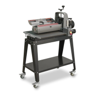
USING THE DEPTH GAUGE
The depth gauge (see Fig. 16) measures the distance
between the conveyor table and the sanding drum
for thickness dimensioning of boards. To calibrate
the depth gauge, raise the conveyor table until the
drum(s), wrapped with abrasive, touches the con-
veyor table. Loosen the two slotted screws holding
the indicator needle to the table mount bracket
(Fig. 16). Raise or lower the indicator needle to read
at zero and tighten the two slotted screws.
USING THE PROSCALE
™
DEPTH GAUGE
The ProScale depth gauge (Page 35, Fig. 45A) has
its own manual. The ProScale can be calibrated by
raising the conveyor until the drum(s) are touching
the conveyor and zero the readout. Another calibra-
tion method is to sand a piece of wood, measuring
the thickness of the wood and change the reading
on the ProScale. See included ProScale manual for
details on calibrating and operation.
USING THE DEPTH STOP
A depth stop (Fig. 16) is located on the column
tube just above the tale support casting on the right
(inboard) side. The depth stop casting has a lock-
ing knob located on one side of the casting. To
operate the depth stop: Determine desired thick-
ness of sanded part by either referencing the depth
gauge or sanding a part and measuring the thickness
of the sanded part. At this sanding thickness, posi-
tion the depth stop along the column tube with the
gauge resting on the table support casting and tight-
en the locking knob on the depth stop. This will
give a desired exiting thickness to the material and
help prevent under dimensioning.
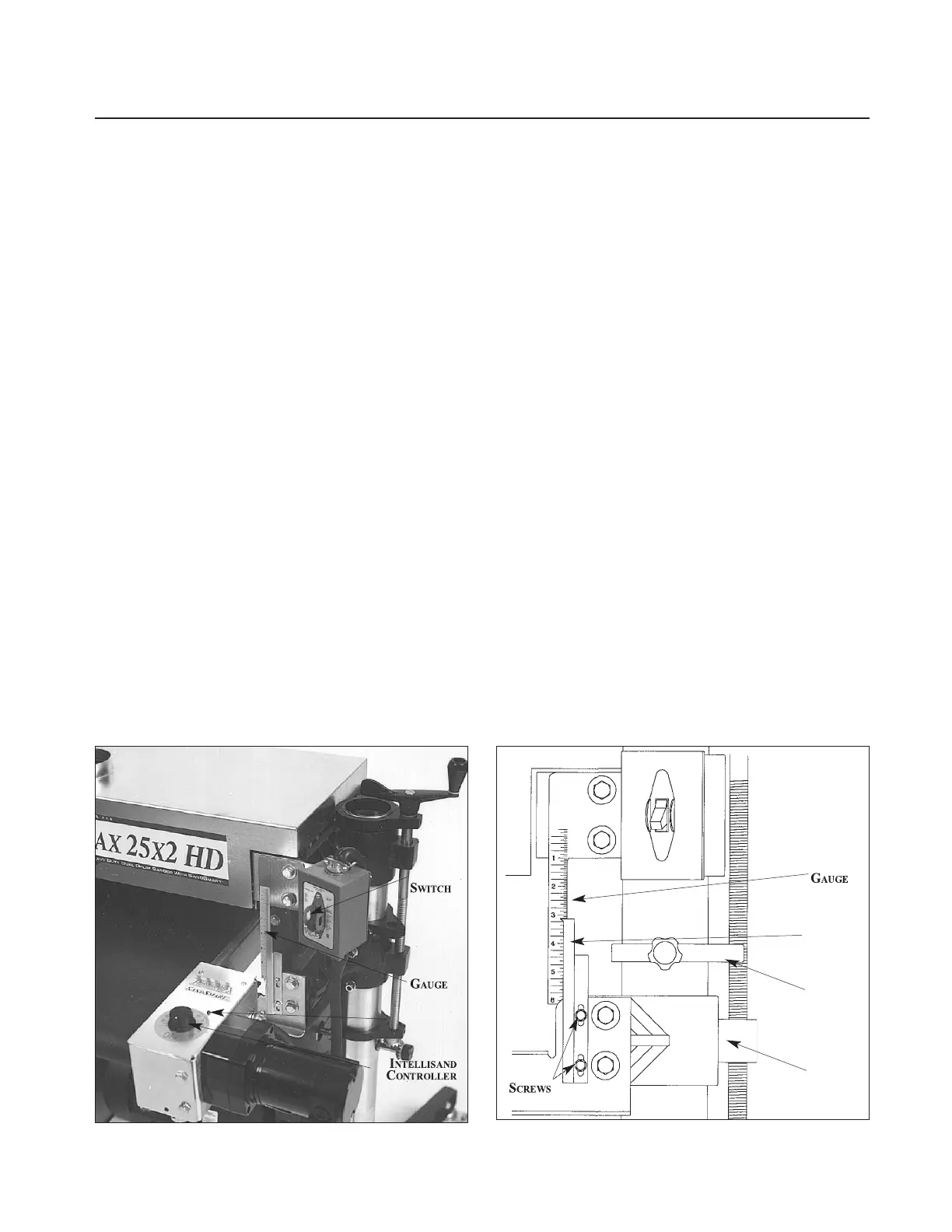
Fig. 15. Intellisand Controller and depth gauge.
Fig. 16. Depth gauge components, on some models.
DRUM
DEPTH
INDICATOR
LIGHT
CALE
EEDLE
EPTH