24 SUPERMAX OWNER’S MANUAL
SERVICING YOUR SUPERMAX
The basic adjustment procedures for your machine
are covered under Setting Up Your SUPERMAX
Sander, page 6. Review that section first. If follow-
ing the general instructions does not solve a specif-
ic problem or result in smooth operation, also
check Troubleshooting Your SUPERMAX, page 19.
Below are suggested procedures to follow when
more thorough readjustment or replacement is
necessary.
ADJUSTING HEIGHT CONTROLS
Height adjustment problems may be the result of
not loosening the set screws in the table support
castings before attempting operation. (This is cov-
ered on page 5 of this manual, and also on the sep-
arate unpacking sheet which was shipped with
your machine.) If the set screws were not loosened
as instructed, do so now before proceeding further.
Also make sure all moving parts of the height
adjusting mechanism are well lubricated, including
the miter gears, column tubes, and threaded
height adjusting screws.
When troubleshooting the height adjustment
mechanism, first check the conveyor table for level
(see page 7). Then test the height adjustment
mechanism (See Fig. 19). If it does not operate
easily, further adjustments may be necessary, as
outlined below. Following these steps should result
in smooth operation.
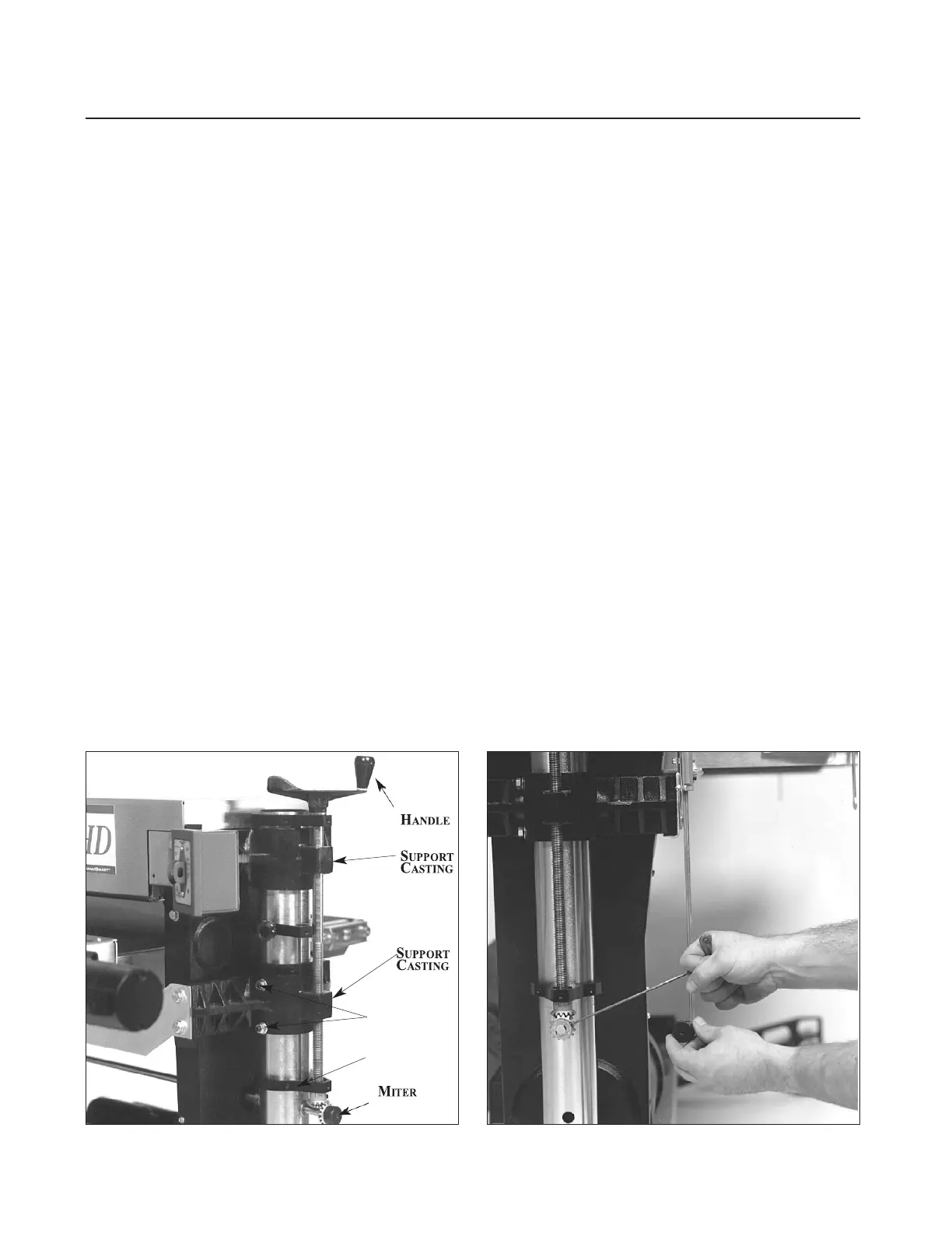
Readjustment Procedure
1. Loosen the set screws located at the front of the
table support castings (Fig. 19).
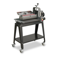
2. Lubricate thoroughly by applying penetrating
lubricant to the table support castings where they
contact the column tubes, and to all contact points
of adjusting screws and cross bar (Fig. 20). Also
apply oil or grease to the miter gears.
3. If the height adjustment feels stiff, check for
misalignment of adjusting screw supports and the
drum support castings which could cause binding
on the adjusting screw rods (Fig. 19). These cast-
ings can be adjusted by loosening the set screws
which secure them to the column tubes. Realign
the adjusting screw supports by loosening the two
set screws that hold them to the column tubes and
rotate to the proper position.
4. The adjusting screw supports located immedi-
ately below the height adjustment handle and the
Fig. 19. Table support casting set screws. Fig. 20. Adjusting miter gears for proper mesh.
H
ADJ.
DRUM
TABLE
HEX NUT
SET SCREW
ADJ. S
SUPPORT
GEAR