6 SUPERMAX OWNER’S MANUAL
SETTING UP YOUR SUPERMAX
Your SUPERMAX drum sander was adjusted and
aligned at the factory, and it has been carefully
packed for shipment. However, because of possible
stress during transit, the unit should be thoroughly
checked before being put to use. This section cov-
ers the pre-operational checks you should make
after unpacking and final assembly. Unnecessary
problems can be avoided if these essential checks
are performed before operating the sander.
Likewise, performing the recommended monthly
maintenance procedures listed at the end of this
section will help assure trouble-free service.
M
AKING
E
LECTRICAL
C
ONNECTIONS
A cord and plug are not included. Consult with
an electrician and confirm all applicable
electrical codes before wiring. Please see wiring
diagrams on pages 36 and 37 for details.
Single Phase: The drum(s) of all SUPERMAX
single phase sanders are powered by a 5 HP, 208-
230 volt, single phase motor. A plug and cord
is not supplied. Single phase SUPERMAX
sanders require a minimum dedicated circuit of
10-gauge wire protected by a 30-amp fuse or
breaker. Extension cords are not recommended,
but if used, should be of at least 10-gauge wire for
lengths up to 10' and of at least 8-gauge wire for
longer lengths.
Three Phase: The drums of SUPERMAX three
phase sanders are powered by a 5 hp, 208-230
volt, three phase motor. Three phase machines
do not include a cord or plug. Three phase
SUPERMAX sanders require a minimum dedicated 20-
amp circuit. Extension cords are not recommended,
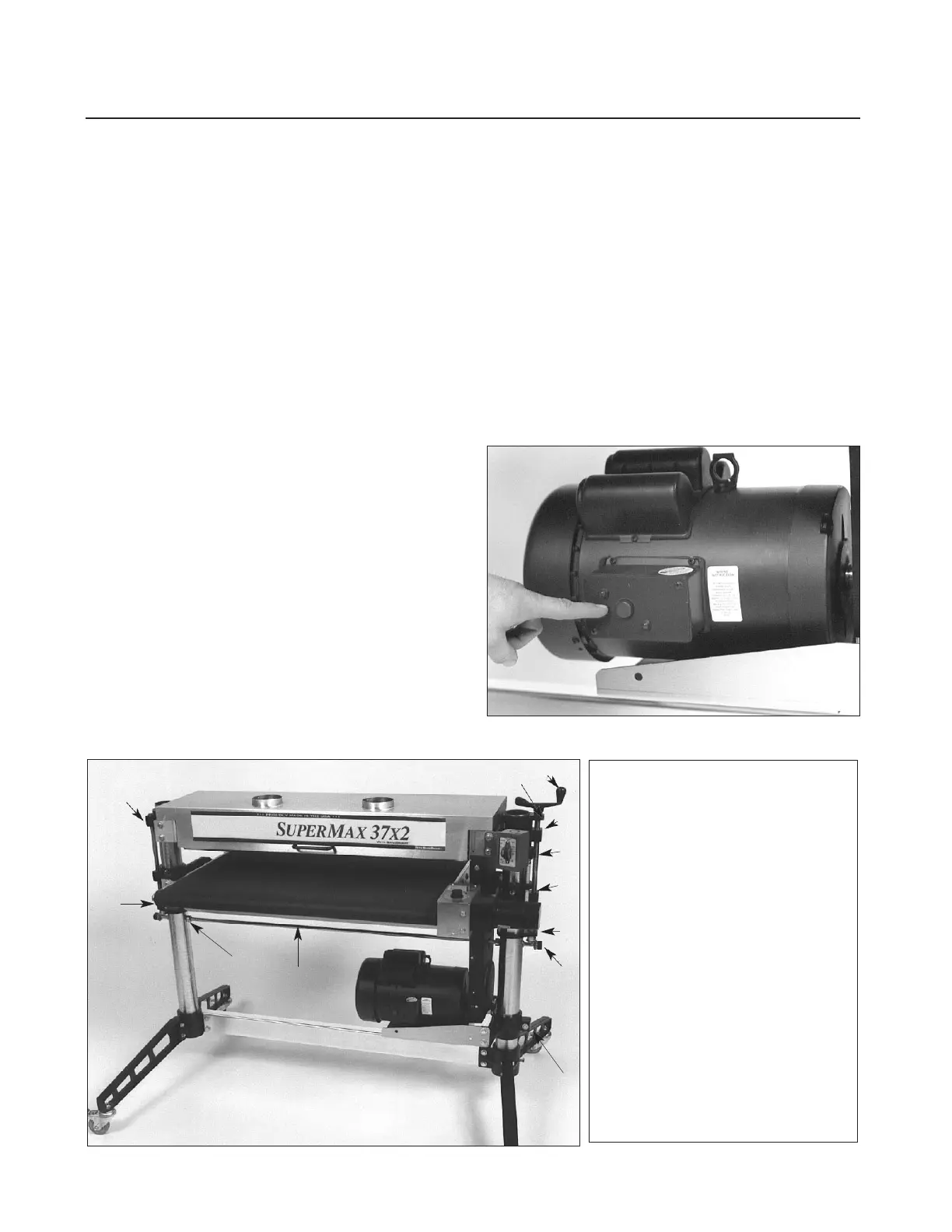
Fig. 4. Thermal-overload switch, on some models.
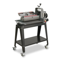
Fig. 5. SUPERMAX Components.
1.
Height Adjustment Handle.
2.
Adjusting Screw Support.
3.
Drum Support Casting.
4.
Height Adjusting Screw.
5.
Table Support Casting.
6.
Adjusting Screw Support.
7.
Miter Gear.
8.
Motor Support Casting.
9.
Transfer Rod.
10.
Shaft Collars.