INBOARD
KNOB
SHAFT
INDICATOR
NEEDLE
SCALE
HEX NUT
8 SUPERMAX OWNER’S MANUAL
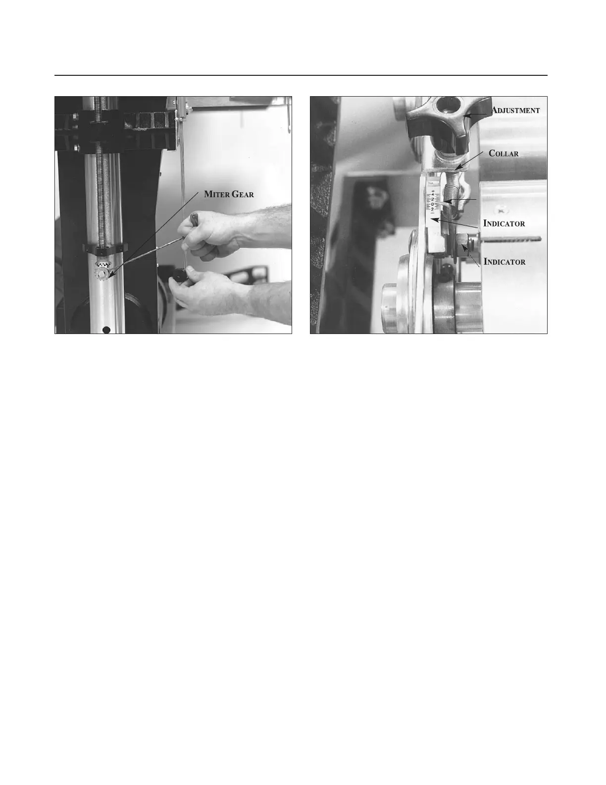
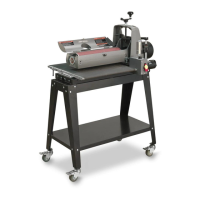
Fig. 8. Adjusting primary drum alignment. Fig. 9. Rear drum adjustment indicator.
the right (inboard) miter gear (see Fig. 8), finely
raise or lower the right (inboard) side of the table
to achieve parallel alignment of the front (primary)
drum. The distance between the conveyor table
and both sides of the front drum should be the
same. Reinstall the miter gear, aligning the set
screw to the flat of the shaft.
Dual Drum Models: Before altering this con-
veyor table position, also check to see that the rear
drum (dual drum models only) is likewise parallel
to the conveyor table, with both sides at the same
height above the table. Using the same thickness
gauge, check both sides of the rear drum from the
rear of the machine while holding up the rear ten-
sion roller. Adjustment of the rear drum is done by
using the right and left drum adjustment knobs
(see Fig. 9).
After the rear drum is adjusted, it is important to
reset the rear drum adjustment indicators to zero
on both sides. Set the secondary drum adjustment
indicators by loosening hex nut, then moving the
indicator scale so that the zero mark is directly
under the needle, and retightening the hex nut
(see Fig. 9). Likewise, zero the indicator for other
side of drum. Take care not to overtighten the hex
nut of the indicator. This can flare the brass bush-
ing and render the indicator inoperable.
Also check that the secondary drum adjustment
knobs turn with a slight resistance to avoid any
movement during operation. To adjust knob resis-
tance, turn the knob clockwise to reveal the set
screw on the shaft collar below the bracket, then
loosen the screw. Making sure the adjustment
knob is tightly seated on top of the bracket, raise
the shaft collar up against the bracket from below
and retighten the set screw.
Note: The nut of the
rear bolt on the rear (secondary) drum bearing
bracket should be backed off a quarter-turn
from being fully tightened. This allows the lock
washer to be depressed slightly but not complete
-
ly. This is the pivot point for the rear drum.
CHECKING THE CONVEYOR BELT
Conveyor belt tension and tracking adjustments
may occasionally be necessary during break-in and
normal operation to compensate for belt stretching.
Install Ceramic Guides at this time. See the
Ceramic Guides instruction sheet inside Ceramic
Guides box, for details. Ceramic Guides are pack-
aged separate on sander.
Belt Tension. To adjust the tension of the convey-
or belt, first adjust the take-up screw nut (see Fig.
10) on both sides of the conveyor to obtain approxi-
mately equal tension on both sides of the belt when
taut. Insufficient belt tension will cause slippage of
conveyor belt on the drive roller during sanding
operation. The conveyor belt is too loose if it can be
stopped by hand pressure applied directly to the top
of the conveyor belt. Excessive belt tension can