HANDLE
DRUM
TABLE
HEX NUT &
GEAR
ADJ.
KNOB
SHAFT
INDICATOR
NEEDLE
SCALE
HEX NUT
SERVICING YOUR SUPERMAX
27
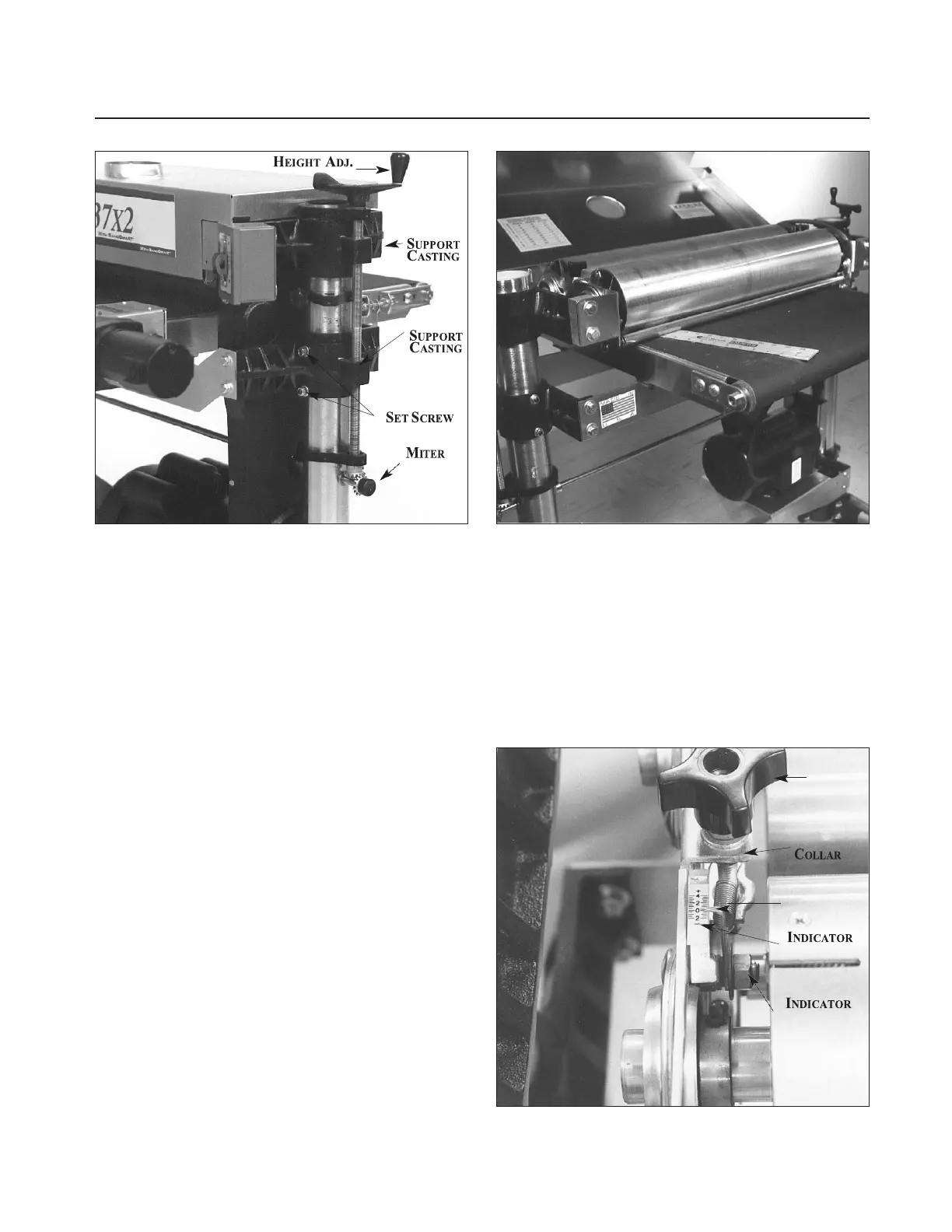
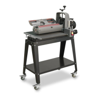
Fig. 25. Adjusting primary drum. Fig. 26. Using thickness gauge during alignment.
ment of the drum (see Adjusting Table Level,
page 7). Note that if only fine adjustment of the
primary drum alignment is required, these adjust-
ment procedures can be used to correct alignment
without relieving V-belt tension or adjusting ten-
sion rollers as described above.
The above procedure is all that is required to
align the drum on a single drum SUPERMAX
sander. If yours is a dual drum machine, follow the
procedure below.
Secondary Drum Alignment. With the primary
drum properly aligned, use the same thickness
gauge and insert it between the secondary drum
and the table from the back side of the machine.
(Again, adjust the contact between the drum and
guide so the drum can barely be turned by hand.)
Measure at both sides of the drum to check that
the secondary drum is parallel to the table. To
adjust the secondary drum alignment, use the
right and left drum adjustment knobs (Fig. 27) to
raise or lower each side of the drum.
At this point both the primary and secondary
drums will be aligned parallel to the table and both
drums will be at the same height above the table.
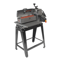
Set the secondary drum adjustment indicators by
loosening the hex nut (Fig. 27), moving the scale so
that the zero mark is directly under the needle, and
retightening the hex nut. Zero the indicator for
other side of drum in the same manner.
Caution: Do not overtighten the hex nut of the
indicator (Fig. 27). This can flare the brass bush-
ing and render the indicator inoperable. Also, the
secondary drum adjustment knobs should turn
with a slight resistance to avoid any movement
during operation. To adjust knob resistance, turn
the knob clockwise to reveal the set screw on the
Fig. 27. Secondary drum adjustment indicator.