34 SUPERMAX OWNER’S MANUAL
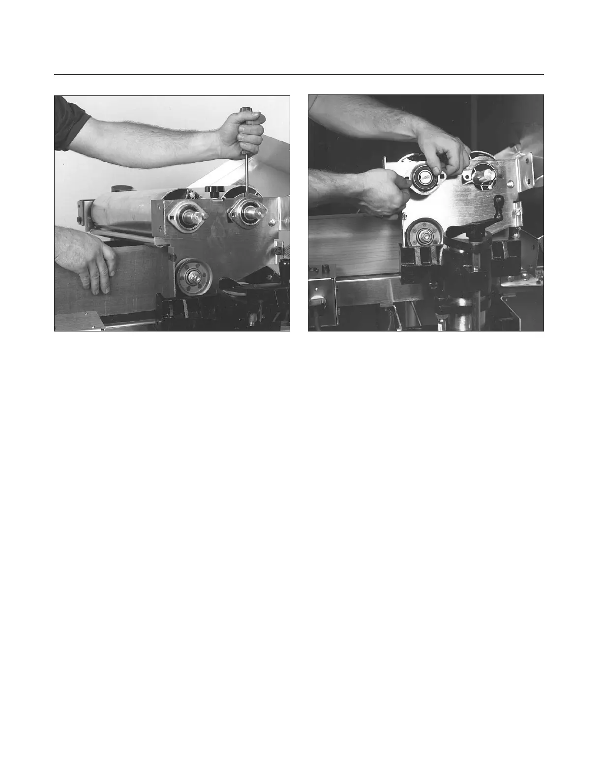
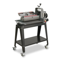
Fig. 41. Removing rear drum bearing. Fig. 42. Removing front bearing (inboard side).
Bearing Replacement (Left Side).
If replacing all
bearings, work first on the bearings on the left (or
outboard) side of the sander first, one at a time,
starting with the rear drum on dual drum sanders.
(Follow Steps 1 through 3 for the bearing on the
left side of single drum sanders, but do not loosen
the rear bolt as instructed in Step 3.)
1. Begin by removing the outer half of the bearing
flange. Loosen the set screws in the bearing collars
and remove the bearing (Fig. 41).
2. If the shaft of the drum is rough from the set
screws, use emery cloth or sandpaper to smooth
down any raised edges. Slide the new bearing on
the shaft, but do not tighten the set screws yet.
3. Install the outer half of the original bearing
flange and tighten the bolts on the rear drum.
After tightening the rear bolt in the flange, loosen
it approximately 1/4 turn, which allows the rear
drum to pivot. Then tighten the set screw in the
bearing collar (Fig. 43).
4. Now move to the front drum and repeat Steps 1
through 3, but do not loosen the rear bolt as
instructed in Step 3. Important: Be sure to note
the sequence of parts used for the rear drum indi-
cator assembly. Also, when reinstalling, do not
over-tighten the nut that holds the indicator in
place (see exploded view, page 43).
Bearing Replacement (Right Side). If the left
(outboard) bearings are the only ones that need
changing, proceed to reassemble the unit. You can
check the drums at this point by lowering the con-
veyor bed and spinning the drums by hand. This
will help determine if the inboard bearing(s) need
to be changed to eliminate noise or excessive play
in the drum.
1. With the drums resting on the conveyor bed,
proceed as follows. Remove the four 3/8" x 1 1/4"
bolts from the drum support casting on the right
side, remove the on/off switch and depth gauge
with the bolts.
2. Next, remove the upper two 3/8" x 1 1/4" bolts
from the drum support casting on the left (out-
board) side of the sander. Loosen the bottom two
3/8" x 1 1/4" bolts from the left drum support
casting, but do not remove them.
3. Lift the right (inboard) side of drums and place
a 2x6 on edge under the drums. Loosen and
remove the V-belt pulleys from drum shafts (see
Fig. 39). Important: Make sure to note the loca-
tion of the pulleys. Also measure the distance from