Chapter 2: Installation
2-29
2-8 Jumper Settings
Explanation of Jumpers
To modify the operation of the mother-
board, jumpers can be used to choose
between optional settings. Jumpers
create shorts between two pins to
change the function of the connector.
Pin 1 is identied with a square solder
pad on the printed circuit board.
Note: On two-pin jumpers, "Closed"
means the jumper is on the pins, and
"Open" means the jumper is off.
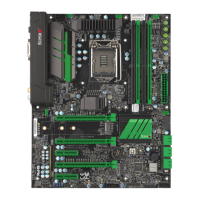
A. JPL1
B. JPL2
LAN Enable/Disable
Jumpers JPL1 and JPL2 will enable or dis-
able the LAN ports 1 and 2, respectively,
on the motherboard. See the table on
the right for jumper settings. The default
setting is enabled.
GLAN Enable
Jumper Settings
Pin# Denition
1-2 Enabled (Default)
2-3 Disabled
JBR1
S5S10
S6
S9S7
SP1
48
B1
JBT1
JSTBY1
JD1
OC_FRONT_PANEL
JF1
1
2
1516
JSD1
FAN5
FAN1
FAN4
FAN2
FAN3
S8
S11
JTPM1
1
1
13
LED2
A
JPW2
JL2
JI2C2
JI2C1
JSPDIF_OUT
JL1
LED4
MH12
MH11
MH10
JVR1
JPL2
JLED1
JPAC1
JPL1
JWD1
JPME2
C7Z170-OCE
REV:1.00
BIOS
LICENSE
MAC CODE
BAR CODE
LAN2
0/1
PCIE M.2 CONNECTOR
USB10(3.1)
LED
PWR NIC
LED
HDD
OH/FF
1
RST
X
ON
PWR
USB8/9(3.0)
USB6/7(3.0)
LAN1
I-SATA4
I-SATA5
BIOS Restore
CLEAR CMOS
KB/MOUSE USB
USB2/3
USB4/5
USB11/12(3.1)
I-SATA1
I-SATA3
I-SATA2
DIMMB2
DIMMB1
DIMMA2
DIMMA1
HDMI/DP/SPDIF
PCH SLOT1 PCI-E 3.0 X1 (IN X4)
CPU SLOT2 PCI-E 3.0 X16
PCH SLOT3 PCI-E 3.0 X1 (IN X4)
CPU SLOT4 PCI-E 3.0 X8 (IN X16)
CPU SLOT6 PCI-E 3.0 X16
CPU FAN
AUDIO FP
HD AUDIO
JF1
ALWAYS POPULATE GREEN SOCKET FIRST
UNB NON-ECC DDR4 DIMM REQUIRED
COM1
DVI
LED1
S12
I-SATA0
JPW1
DESIGNED IN USA
CPU Socket LGA1151
PCH
Z170
2
NIC
A
B
 Loading...
