12
H11DSi / H11DSi-NT User's Manual
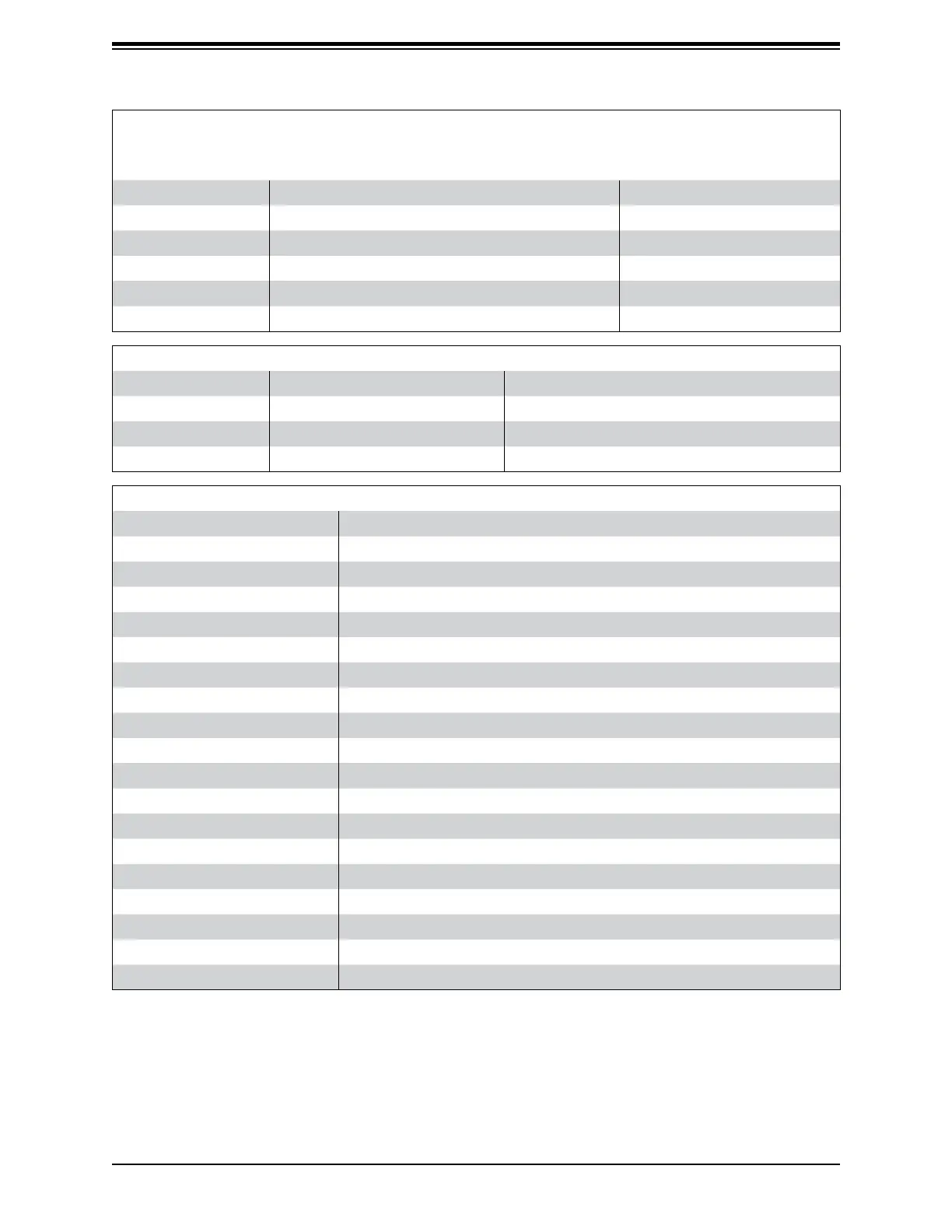
Quick Reference Table
Jumper Description Default Setting
UID SW Unit ID Switch (push-button toggle switch ON/OFF) Off
JI2C1 / JI2C2 PCI-E Slot SMB (System Management Bus) Enable/Disable Pins 2-3 (Disabled)
JBT1 CMOS Clear Open (Normal)
JPG1 VGA Enable/Disable Pins 1-2 (Enabled)
JPL1 LAN Enable/Disable Pins 1-2 (Enabled)
JWD1 Watch Dog Pins 1-2 (Reset)
LED Description Status
UID LED Unit ID LED Solid Blue: UID Switched to ON
LED2 Onboard Overheat / Fan Failure Solid Red: System Overheat, Blinking Red: Fan Failure
LED3 Onboard Power LED Off: Sytem Off, Solid Green: System ON
LEDM1 BMC Heartbeat LED Blinking Green: Normal
Connector Description
JIPMB1 System Management Bus Header
COM1 COM Port
FANA, FANB, FAN1~FAN6 4-pin System/CPU Fan Headers
P2-SATA0, P2-SATA1 SATA 3.0 Ports for SATA/DOM with integrated power
CPU1-SATA0-3, CPU2-SATA0-3 Connectors for SATA0~3, use iPass breaklout cable (4 ports each)
JF1 Front Control Panel Header 1
JL1 Chassis Intrusion Header
LAN1/LAN2 RJ45 LAN Port (H11DSi-NT supports 10Gb)
IPMI LAN Gigabit LAN (RJ45) Port for IPMI
JPWR1 24-pin Main Power Connector
JPWR2/JPWR3 8-pin Auxilliary Power Connectors
JSD1/JSD2 SATA DOM (Device on Module) power connectors 1/2
JMD1 M.2 Connector with integrated SATA/PCIe signals
JTPM1 Trusted Platform Module/Port 80 Connector
USB0/1, USB4/5 Back Panel USB Type A Ports for USB0/USB1 (2.0) and USB4/USB5 (3.0)
USB2/3 Front Panel USB Header for USB2/USB3 (2.0).
P2-NVME0/1 Processor 2 NVMe Ports 0/1 for NVMe Hard Disk Drives (H11DSi-NT only)
JSTBY1 Stand-by Power Header
BT1 On-board CMOS Backup Battery

 Loading...