2-12
S
UPER P4SPA+/P4SPE User's Manual
CMOS Clear
JBT1 is not actually a jumper but con-
sists of two contact pads. To clear the
contents of CMOS, short these pads
together by touching them both with a
metal conductor such as the head of
a small screwdriver. JBT1 is located
near the SATA header on the P4SPA+/
P4SPE. Note: For ATX power sup-
plies, you must completely shut down
the system and remove the AC power
cord before clearing CMOS.
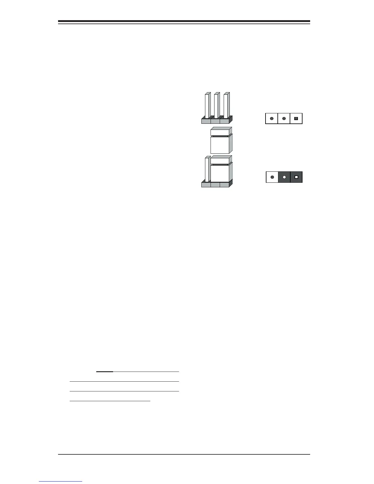
2-7 Jumper Settings
Explanation of
Jumpers
To modify the operation of the mother-
board, jumpers can be used to choose
between optional settings. Jumpers
create shorts between two pins to
change the function of the connector.
Pin 1 is identifi ed with a square solder
pad on the printed circuit board. See
the motherboard layout pages for
jumper locations.
Note: On a two-pin jumper, "Closed"
means the jumper is on both pins and
"Open" means the jumper is either on
only one pin or completely removed.
Connector
Pins
Jumper
Cap
Setting
Pin 1-2 short
3 2 1
3 2 1