Home
Supermicro
Motherboard
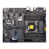
SUPER P6DBE
Supermicro SUPER P6DBE - User Manual
108 pages
Manual
Specs
Ask a question
Save Page as PDF
To Next Page
To Next Page
Loading...
®
SUPER P6DBS
SUPER P6DBE
SUPER P6DBU
SUPER P6SBU
SUPER P6SBS
SUPER P6SBA
SUPER P6SBM
USER’S AND BIOS
MANUAL
Revision 4.0
S
UPER
2
Table of Contents
Main Page
Default Chapter
3
About this Manual
3
Appendix A Offers Information on BIOS Error Beep Codes and Messages.
3
Appendix B Shows Post Diagnostic Error Messages.
3
Manual Organization
3
Preface
3
Table of Contents
5
Jumper Quick Reference
8
Front Control Panel Connector
9
Chapter 1: Introduction
11
Overview
11
SUPER P6DBS Image
14
SUPER P6DBS Motherboard Layout
15
SUPER P6DBE Image
16
SUPER P6DBE Motherboard Layout
17
SUPER P6DBU Image
18
SUPER P6DBU Motherboard Layout
19
SUPER P6SBU Image
20
SUPER P6SBU Motherboard Layout
21
SUPER P6SBS Image
22
SUPER P6SBS Motherboard Layout
23
SUPER P6SBA Image
24
SUPER P6SBA Motherboard Layout
25
SUPER P6SBM Image
26
SUPER P6SBM Motherboard Layout
27
440BX AGP Chipset: System Block Diagram
28
Chipset Overview
31
PC Health Monitoring
31
Solo-1 PCI Audio Drive
34
Super P6Dbs/P6Dbe/P6Dbu/P6Sbu/P6Sbs/P6Sba/P6Sbm
34
ACPI/PC 98 Features
35
Wake-On-LAN
36
Power Supply
37
Super I/O
37
Chapter 2: Installation
41
Static-Sensitive Devices
41
Precautions
41
Unpacking
41
Pentium III/II Processor Installation
41
Installation of the Universal Retention Mechanism
45
Special Instructions for the Celeron Processor
45
Explanation and Diagram of Jumper/Connector
47
Changing the CPU Speed
47
Mounting the Motherboard in the Chassis
48
Connecting Cables
48
Power Supply Connector
48
Secondary Power Connector
48
Infrared Connector
48
PW_ON Connector
49
Reset Connector
49
Hard Drive LED
49
Keylock/Power LED Connector
49
Speaker Connector
50
Power Save State Select
50
Universal Serial Bus
50
ATX Serial Ports
51
CMOS Clear
51
External Battery
51
Wake-On-LAN
51
Fan Connectors
51
CMO Clear
51
Chassis Intrusion
52
PCI Audio Drive Connectors
52
SLED (SCSI LED) Indicator
52
Jpwake
52
Installing Dimms
53
DIMM Installation
53
Connecting Parallel Port, Floppy and Hard Disk Drives
54
Parallel Port Connector
55
Floppy Connector
55
IDE Connectors
55
SCSI Connectors
56
Ultra II LVD SCSI 68-Pin Connector
57
AGP Port
58
Chapter 3: Troubleshooting
59
Troubleshooting Procedures
59
Before Power on
59
Troubleshooting Flowchart
59
No Power
60
No Video
60
Memory Errors
60
Losing the System's Setup Configuration
61
Technical Support Procedures
61
Frequently Asked Questions
62
Returning Merchandise for Service
66
Chapter 4: AMIBIOS
67
Introduction
67
BIOS Features
68
BIOS Configuration Summary Screen
69
AMIBIOS Setup
69
Chapter 5: Running Setup
71
Setup
71
Standard Setup
71
Advanced Setup
73
Chipset Setup
77
Power Management
83
Pci/Pnp Setup
85
Peripheral Setup
88
Security Setup
90
Supervisor/User
90
Utility Setup
91
Anti-Virus
91
Language
91
Default Settings
91
Optimal Defaults
91
Fail-Safe Defaults
91
Need help?
Do you have a question about the Supermicro SUPER P6DBE and is the answer not in the manual?
Ask a question
Supermicro SUPER P6DBE Specifications
Print Specification
General
Form Factor
ATX
Chipset
Intel 440BX
Max RAM
1 GB
IDE Ports
2
USB Ports
2
PCI Slots
4
AGP Slots
1
CPU Socket
Socket 370
Memory Slots
4 x 168-pin DIMM
Related product manuals
Supermicro PDSBA
86 pages
Supermicro X10DRT-P
113 pages
Supermicro X11DPT-PS
107 pages
Supermicro C9Z490-PG
142 pages
Supermicro P4SPA Plus
68 pages
Supermicro C9Z390-PGW
129 pages
Supermicro X9DRG-O-PCIE
119 pages
Supermicro C9X299-PGF-L
129 pages
Supermicro Supero X8DTL-i
101 pages
Supermicro X10DRL-i SUPERO
121 pages
Supermicro Supero X9SRH-7F
115 pages
Supermicro Supero X9DRi-LN4F+
113 pages