Chapter 2: Installation
2-9
PW_ON Connector
The PW_ON connector is located on
pins 9 and 10 of JF2. Momentarily
contacting both pins will power on/off
the system. The user can also con-
figure this button to function as a
suspend button. (See the Power
Button Function in BIOS on page 5-
13.) To turn off the power when set
to suspend mode, hold down the
power button for at least 4 seconds.
See Table 2-5 for pin definitions.
Reset Connector
The reset connector is located on
pins 12 and 13 of JF2. This connec-
tor attaches to the hardware reset
switch on the computer case. See
Table 2-6 for pin definitions.
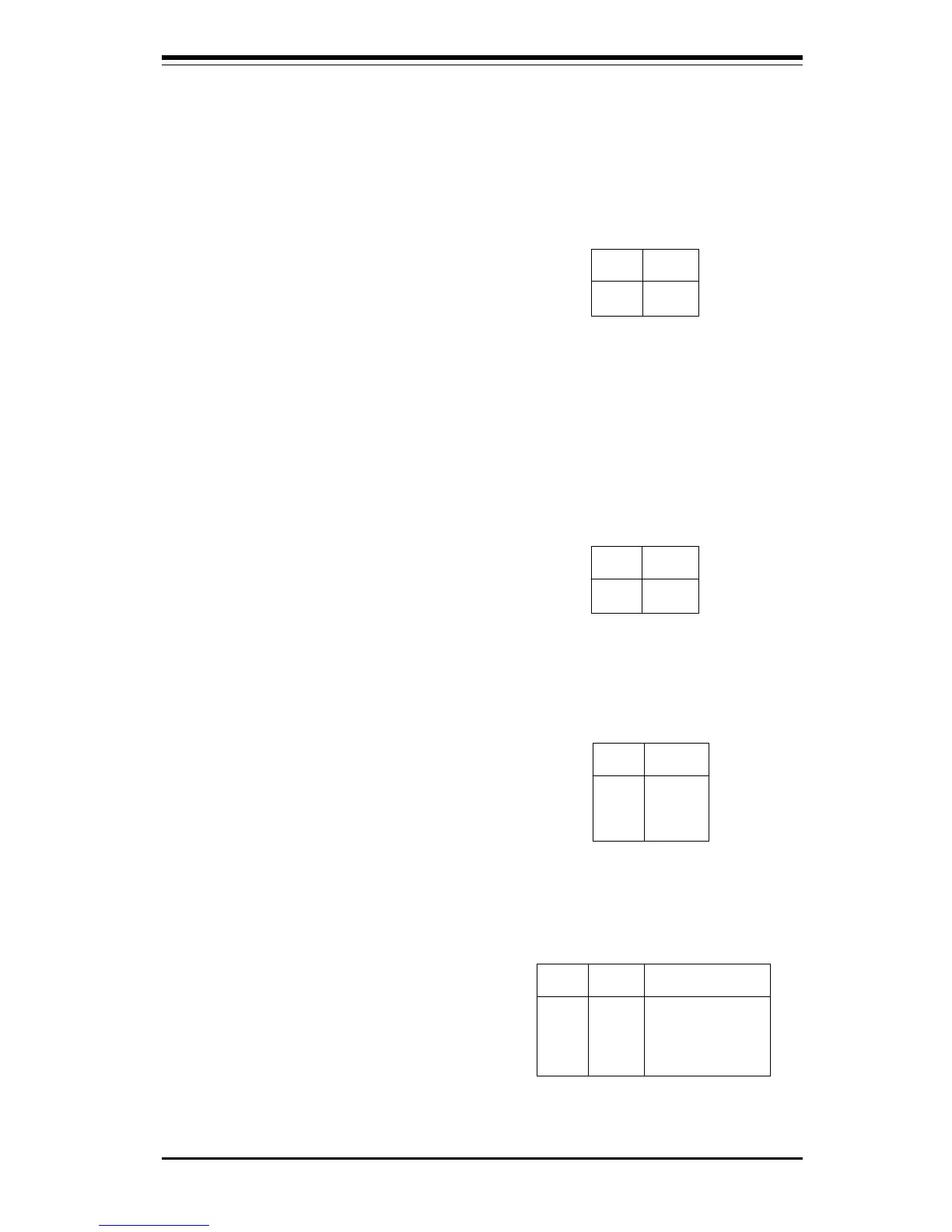
Pin
Number
9
10
Definition
PW_ON
Ground
Table 2-5
PW_ON Connector
Pin Definitions
for JF2
Table 2-7
Hard Drive LED Pin
Definitions
for JF1
Pin
Number
1
2
3
4
Definition
+5V
HD Active
HD Active
+5V
Pin
Number
12
13
Definition
Ground
Reset
Table 2-6
Reset Pin
Definitions
for JF2
Hard Drive LED
The hard drive LED is located on pins
1 to 4 of JF1. Attach the hard drive
LED cable to pins 1 and 2. See
Table 2-7 for pin definitions.
Keylock/Power LED
Connector
The keylock/power LED connector is
located on pins 5 to 9 of JF1. See
Table 2-8 for pin definitions. Pins 5
through 7 are for the power LED.
Pins 8 and 9 are for the keylock.
Note: SMC type I/O controllers do
not support the keylock function.
Pin
Number
5
6
7
8
9
Function
VCC +5V
VCC +5V
Ground
Ground
Table 2-8
Keylock/Power LED Pin Definition
for JF1
Definition
Red wire, LED power
Red wire, LED power
LED control
Keyboard inhibit
Black wire