2-10
SUPER P6DBS/P6DBE/P6DBU/P6SBU/P6SBS/P6SBA/P6SBM Manual
Jumper
Position
1-2
2-3
Definition
PIIX4E Ctrl
Save PD State
Table 2-10
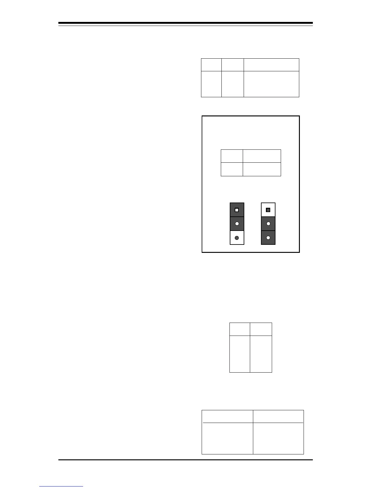
Power Save State Select
Pin Definitions
for JP20
Position
1-2
Position
2-3
PIIX4E Ctrl
Save PD State
Table 2-9
Speaker Connector Pin Definitions for
JF1
Pin
Number
10
11
12
13
Function
+
Key
Definition
Red wire, Speaker data
No connection
Key
Speaker data
Speaker Connector
The speaker connector is located on
pins 10 to 13 of JF1. See Table 2-9
for pin definitions.
Power Save State Select
Refer to Table 2-10 to set JP20. The
Power Save State Select is used
when you want the system to remain
in the power-off state when you first
apply power to the system or when
the system recovers from an AC
power failure. In this state, the
power will not come on unless you
hit the power switch on the mother-
board. PIIX4E control is used if you
want the system to be in the power-
on state the first time you apply
power to the system or when the
system recovers from an AC power
failure.
Table 2-11
ATX PS/2
Keyboard
and PS/2 Mouse
Pin Definitions
for J34
Pin
Number
1
2
3
4
5
6
Definition
Data
NC
Ground
VCC
Clock
NC
Table 2-12
Universal Serial Bus Pin Definitions
Pin
Number Definition
1 +5V
2 P0-
3 P0+
4 Ground
5 N/A
Pin
Number Definition
1 +5V
2 P0-
3 P0+
4 Ground
5 Key
J17
J18
ATX PS/2 Keyboard and
PS/2 Mouse Ports
The ATX PS/2 keyboard and the
PS/2 mouse are located on J34.
See Table 2-11 for pin definitions.
(PS/2 Keyboard: J35 bottom, PS/2
Mouse: J35 top)
Universal Serial Bus
The two Universal Serial Bus con-
nectors are located on J17 and
J18. See Table 2-12 for pin defini-
tions.