Chapter 2: Installation
2-11
Table 2-13
ATX Serial Port Pin Definitions
Pin Number Definition
1 DCD
2 DSR
3 Serial In
4 RTS
5 Serial Out
Pin Number Definition
6 CTS
7 DTR
8 RI
9 Ground
10 NC
J20
J21
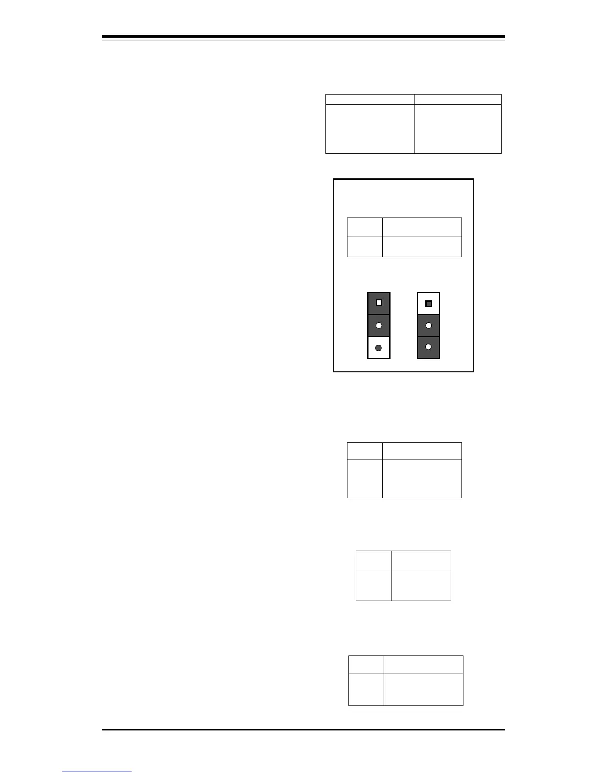
Table 2-14
CMOS Clear Pin Definitions
for JBT1
Jumper
Position
1-2
2-3
Definition
Normal
CMOS Clear
Position
1-2
Position
2-3
Normal
CMOS Clear
Table 2-17
Fan Connector Pin Definitions
for JT1, JT2, JT3
Pin
Number
1
2
3
Definition
Ground (black)
+12V (red)
Tachometer
* Caution: These fan connectors
are DC direct.
Pin
Number
1
2
3
4
Definition
+3V
NC
NC
Ground
Table 2-15
External Battery Pin
Definitions
for JBT2
CMOS Clear
Refer to Table 2-14 for instructions
on how to clear CMOS. For an ATX
power supply, you must com-
pletely shut down the system,
then use JBT1 to clear CMOS. Do
not use the PW_ON connector to
clear CMOS. A second way of re-
setting the CMOS contents is by
pressing the <Ins> key and then
turning on the system power. Re-
lease the key when the power comes
on.
ATX Serial Ports
ATX serial port COM1 is located
on J20 and serial port COM2 is
located on J21. See Table 2-13
for pin definitions.
External Battery
Connect an external battery to JBT2.
Refer to Table 2-15 for pin defini-
tions. (Not on P6SBM.)
Pin
Number
1
2
3
Definition
+5V Standby
Ground
Wake-up
Table 2-16
Wake-On-LAN Pin
Definitions (WOL)
Wake-On-LAN
The Wake-On-LAN connector is lo-
cated on WOL. Refer to Table 2-16
for pin definitions.
Fan Connectors*
The thermal/overheat fan is located
on JT3. The CPU fans are located on
JT1 and JT2. Refer to Table 2-17 for
pin definitions.