Chapter 2: Installation
2-7
2-5 Explanation and
Diagram of Jumper/
Connector
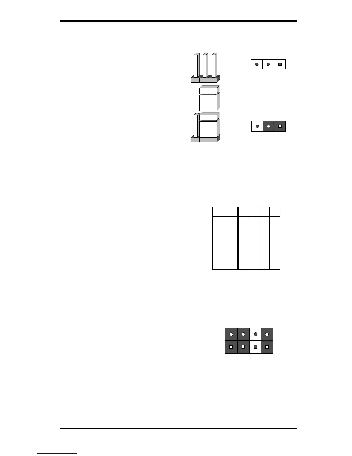
To modify the operation of the
motherboard, jumpers can be used
to choose between optional set-
tings. Jumpers create shorts be-
tween two pins to change the
function of the connector. Pin 1 is
identified with a square.
2-6 Changing the CPU
Speed
To change the CPU speed for a
Pentium III/II processor, change the
jumpers shown in Table 2-1. The
example on the right will show you
which CPU Core/Bus Ratio to use.
The general rule is to divide the
CPU speed by the bus speed (100
MHz in this example). If you have
a 400 MHz CPU, dividing it by 100
will give you a CPU Core/BUS Ra-
tio of 4.0. After determining the
CPU Core/Bus Ratio, refer to Table
2-1 for the correct settings of JB1,
JB2, JB3 and JB4.
3 2 1
Connector
Pins
Jumper
Cap
Setting
Pin 1-2 short
400 MHz = 100 MHz x 4.0
CPU Speed = Bus Freq. x Ratio
Example of 4.0
CPU Core/Bus Ratio
JB1 JB2 JB3 JB4
ON ON OFF ON
CPU Core/
Bus Ratio
3.0
3.5
4.0
4.5
5.0
5.5
6.0
6.5
7.0
7.5
8.0
JB1
ON
OFF
ON
OFF
ON
OFF
ON
OFF
ON
OFF
ON
JB2
OFF
OFF
ON
ON
OFF
OFF
ON
ON
OFF
OFF
ON
JB3
ON
ON
OFF
OFF
OFF
OFF
ON
ON
ON
ON
OFF
JB4
ON
ON
ON
ON
ON
ON
OFF
OFF
OFF
OFF
OFF
Table 2-1
CPU Core/Bus Ratio Selection