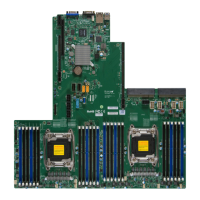
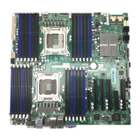
SUPER P6DBS/P6DBE/P6DBU/P6SBU/P6SBS/P6SBA/P6SBM Manual
viii
P6DBS/P6DBE/P6SBS/P6SBA/P6SBM* P6DBU/P6SBU
Jumpers
JB1, JB2, JB3, JB4
JBT1
JP20
JL2
JA5
JA6
JOH
JP11
JPWAKE
Connectors
J17
J18
J19
J20
J21
J32
J34
J36
JBT2
JF1
JF2
JL1
SLED
JT1
JT2
JT3
WOL
Function Page
CPU/Bus Ratio Selection 2-7
CMOS Clear 2-11
Power Save State Select 2-10
Manufacturer Default 1-5
JA1, JA3, SCSI Termination
(default on as terminated) 1-5
JA2 SCSI Termination
(default on as terminated) 1-5
Overheat LED Header 1-5
Bus Speed 1-5
System Wake-up (P6SBM only) 2-12
Function Page
USB 2-10
USB 2-10
Parallel Port 2-15
COM 1 2-11
COM 2 2-11
Power Supply Connector 2-8
PS/2 KB and Mouse 2-10
Secondary Power Connector 2-8
External Battery (not on P6SBM) 2-11
IDE LED 2-9, 2-10
Keylock
Speaker
IR Connector 2-8, 2-9
PW_ON
Reset
Chassis Intrusion 2-12
SCSI LED 2-12
CPU 1 Fan 2-11
CPU 2 Fan 2-11
Thermal Control Fan 2-11
Wake-On-LAN 2-11
Jumpers
JB1, JB2, JB3, JB4
JBT1
JP20
S-TERM
JOH
JPS1
BZ_ON
JP11
Connectors
J17
J18
J19
J20
J21
J32
J34
J36
JA2
JA1
JA3
JBT2
JF1
JF2
JL1
SLED
JT1
JT2
JT3
WOL
Function Page
CPU/Bus Ratio Selection 2-7
CMOS Clear 2-11
Power Save State Select 2-10
SCSI Termination
(default on as terminated) 1-9
Overheat LED Header 1-9
PCI Audio Enable/Disable 1-9
Overheat Alarm Enable 1-9
Bus Speed 1-9
Function Page
USB 2-10
USB 2-10
Parallel Port 2-15
COM 1 2-11
COM 2 2-11
Power Supply Connector 2-8
PS/2 KB and Mouse 2-10
Secondary Power Connector 2-8
UW SCSI 2-16
Ultra II LVD/SE 2-17
Ultra SCSI 2-16
External Battery 2-11
IDE LED 2-9, 2-10
Keylock
Speaker
IR Connector 2-8, 2-9
PW_ON
Reset
Chassis Intrusion 2-12
SCSI LED 2-12
CPU 1 Fan 2-11
CPU 2 Fan 2-11
Thermal Control Fan 2-11
Wake-On-LAN 2-11
*Note: SCSI jumpers and connectors do not apply to the P6DBE,
P6SBA or P6SBM motherboards.
5-4 Default Settings ............................................................................................. 5-21
5-4-1 Optimal Defaults ........................................................................... 5-21
5-4-2 Fail-Safe Defaults ........................................................................ 5-21
Appendices:
Appendix A: BIOS Error Beep Codes and Messages ....................................... A-1
Appendix B: AMIBIOS Post Diagnostic Error Messages .................................... B-1
Jumper Quick Reference
 Loading...


