Do you have a question about the Supermicro SC946ED-R2KJBOD and is the answer not in the manual?
Explains the manual's purpose and intended audience, guiding professional system integrators and PC technicians.
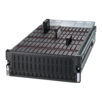
Describes the SC946ED storage enclosure, highlighting its high-density design, expander modules, and cooling fans.
Directs users to the Supermicro website for the latest shipping lists and part numbers for their chassis model.
Advises users to purchase replacement parts exclusively from Supermicro Authorized Distributors/System Integrators/Resellers.
Provides contact information for Supermicro headquarters, Europe, and Asia-Pacific regions.
Details the process for obtaining warranty service, including RMA procedures and packaging instructions for returns.
Explains the purpose of standardized warnings, recommending professional installation and reading the appendix before setup.
Defines the warning symbol as indicating danger and potential bodily injury, advising awareness of electrical hazards.
Instructs users to read installation procedures before connecting the system to a power source.
Warns that the product relies on building's short-circuit protection, specifying a maximum rating of 250 V, 20 A.
Mandates disconnecting all power sources and removing power cords before accessing the chassis interior.
States that only trained and qualified personnel should install, replace, or service the equipment.
Indicates the unit is for installation in restricted access areas, requiring special tools or security for entry.
Warns of explosion danger if batteries are replaced incorrectly and advises proper disposal.
States that all power connections must be removed to de-energize the unit, as it may have multiple power supply connections.
Warns of hazardous voltage or energy on the backplane during operation and advises caution during servicing.
Emphasizes that equipment installation must comply with all local and national electrical codes.
Instructs that ultimate disposal of the product must follow all national laws and regulations.
Warns that fans may still be turning when removed and advises keeping fingers and tools away from openings.
Advises using only provided or designated cables/adapters to prevent malfunction or fire, citing law prohibiting unauthorized UL/CSA cables.
Introduces the control panel LEDs and buttons, explaining their role in informing users about system status and activity.
Describes the two push-buttons on the chassis control panel: Power and UID/IPMI reset.
Details the five LEDs on the control panel, explaining their indications and necessary corrective actions.
Indicates network activity on the primary (NIC1) and secondary (NIC2) expanders when flashing.
Describes the status and meaning of various informational LEDs, including overheat, fan failure, power failure, and UID status.
Explains the blue and red LED indicators on SAS3 drive carriers for drive status, activity, and failure.
Identifies LEDs, connectors, and components on the rear of the chassis, including power supplies, fans, and ports.
Introduces the chapter on chassis setup and maintenance, emphasizing safety warnings and tool requirements.
Details the specific procedures for powering the SC946ED system up and down, including first-time startup and optional IPMI control.
Provides step-by-step instructions for opening and closing the chassis cover, with a warning about operating without it.
Describes the procedure for removing and installing the front panel, which must be done before accessing the backplane tray.
Explains how to remove hot-swappable 3.5" hard drives from their carriers and the chassis.
Details the steps for inserting 3.5" hard drives into the carriers and then installing the carriers into the chassis drive bays.
Outlines the steps required to access the backplane tray, which contains primary backplanes and a mid-plane.
Provides instructions for properly closing and securing the backplane tray after access.
Covers the hot-swappable removal and installation procedures for the expander modules located at the rear of the chassis.
Details the steps for aligning and installing an expander module back into its bay, securing it with the thumbscrew.
Explains the function of the five hot-swappable fans and how to replace a failed system fan.
Describes the redundant 1000W power supplies, their auto-switching capability, and how to change a power supply module.
Provides step-by-step instructions for removing and replacing the power distributor board assembly.
Guides the user through identifying and assembling the components of the cable management arm (CMA).
Details the process of installing CMA connector #1 onto the base of the inner member of the cable management arm.
Explains how to install CMA connector #2 onto the base of the inner member.
Describes the functionality of the cable management arm's swing arm, including right and left movements.
Introduces the chapter on rack installation, offering a quick setup checklist to get the chassis operational quickly.
Guides users on inspecting the chassis shipment for damage and selecting a suitable, well-ventilated rack location.
Lists the items included in the chassis package for rack mounting and advises reading the section before installation.
Lists important rack and general server precautions to ensure safe and stable installation and operation.
Discusses ambient operating temperature, airflow, mechanical loading, circuit overloading, and the need for reliable grounding during rack mounting.
Provides information on installing the chassis into a rack using the rails, including identifying rail sections.
Explains the function of the locking tabs on the inner rails, which secure the chassis in place when installed or extended.
Details the steps to release the inner rail from the outer rail assemblies for installation or servicing.
Guides the user through installing the inner rails onto the chassis, aligning hooks and securing them.
Provides instructions for hanging and securing the outer rails onto the rack slots.
Details the complete process for installing the chassis into the rack, including loading drives, securing locking tabs, and powering up.
Lists the components of the SC946ED chassis backplane system: three backplanes, one midplane, one expander board, and two power distributor boards.
States the revision versions of the backplanes, midplane, expander board, and power distributor board reflected in the manual.
Provides essential guidelines for handling electronic components to prevent damage from Electrostatic Discharge (ESD).
Offers general safety practices, including disconnecting power before component installation/removal and ensuring secure backplane installation.
Introduces cascading configurations, explaining that backplanes can be combined in various ways for different applications.
Details specific cascading configuration options, starting with Single Host (LSI 9300-8E) with one JBOD.
Illustrates cascading configurations for a single host with three JBODs using LSI 9300-8E.
Shows cascading configurations for a single host with one JBOD using LSI 9300-16E.
Depicts cascading configurations for a single host with three JBODs using LSI 9300-16E.
Illustrates cascading configurations for a single host with three JBODs using LSI 9300-8E.
Shows cascading configurations for dual hosts with two JBODs using LSI 9300-8E.
Depicts cascading configurations for dual hosts with two JBODs using LSI 9300-16E.
Illustrates cascading configurations for four hosts with one JBOD using LSI 9300-8E.
Shows cascading configurations for four hosts with one JBOD and zoning, using LSI 9300-8E.
| Form Factor | 4U |
|---|---|
| JBOD | Yes |
| Interface | SAS3 (12 Gbps) |
| Backplane | SAS3/SATA |
| Dimensions (HxWxD) | 178mm |
| Weight | 40 kg |
| Compatibility | Supermicro |