Do you have a question about the Supermicro CSE-826BE1C-R609JBOD and is the answer not in the manual?
Provides information for installation and use of the chassis.
Details symbols used in the manual for safety.
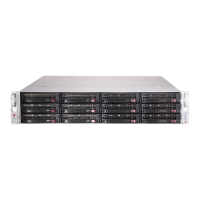
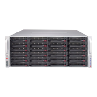
Introduces the SC826 JBOD storage enclosure and its features.
Provides information on shipping lists and part numbers.
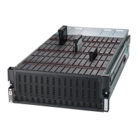
Details the chassis components: drives, power supply, cooling, control board, mounting rails.
Information on purchasing replacement parts from Supermicro.
Procedure for returning items for warranty service.
Provides contact information for Supermicro headquarters and regional offices.
Explains industry-standard warnings for potential bodily injury.
Defines the danger symbol and its meaning for safety.
Describes the chassis front panel, hard drives, and power supply status lights.
Details the power and UID/IPMI reset buttons on the control panel.
Explains the status indicators (LEDs) for power, NIC, and failures.
Covers component installation and maintenance procedures.
Procedures for turning the system on and off.
Instructions for connecting BMC LAN, SAS, and cascading cables.
Step-by-step guide to safely remove the chassis top cover.
Instructions for installing and removing hot-swappable hard drives.
Details on system fans and how to replace them.
Information on hot-swap redundant power supply modules.
Description and location of the JBOD control board.
Instructions for removing and installing the backplane.
Instructions for inspecting the chassis upon arrival.
Guidelines for selecting a suitable installation location.
Safety guidelines for rack and server installation.
Detailed steps for mounting the chassis into a rack using provided rails.
Introduces the JBOD control board and its capabilities.
Covers ESD and general safety precautions for handling components.
Identifies and defines components, connectors, jumpers, and LEDs on the control board.
Instructions for I2C cabling for SAS functionality.
Procedures for powering the system on and off.
Details on the Baseboard Management Controller, including password and IP address.
Specifications for the 650W power supply module.
Provides details on backplane models and features.
Safety precautions for handling backplanes and related components.
Details the revision of the backplane manual.
Diagram and list of rear connectors on the backplane.
Defines the function and pin assignments of rear connectors.
Details jumper locations and their settings for backplane operation.
Explains the status and specification of rear backplane LEDs.
Details front connectors and SAS/SATA drive LEDs.
Describes single and dual port expanders for SAS connectivity.
Explains failover configurations for single host bus adapters.
Details failover with RAID controllers and multiple HBAs.
Information on the JBOD control board in cascaded configurations.
Instructions for connecting external HBAs to the backplane.
Information on SAS cables and adapters.
Cables for cascading from a single HBA.
Cables for cascading from dual HBAs.
Lists regulatory compliance and applied directives/standards.
Specific warning regarding perchlorate materials in lithium coin cells.
| Form Factor | 2U |
|---|---|
| Material | Steel |
| Drive Bays | 12 x 3.5" hot-swap bays |
| Backplane | SAS2/SATA |
| Power Supply | 600W Redundant |
| Cooling | 4 x 80mm Fans |
| Dimensions (HxWxD) | 3.5" (89mm) x 17.2" (437mm) x 25.5" (648mm) |
| Weight | 40 lbs (18.1 kg) |
| Compatibility | SAS/SATA Drives |
| Front Panel | Power Button, Activity LEDs |
| Management | IPMI |