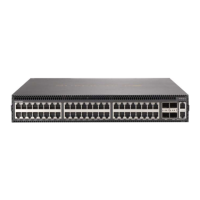
SSE-X3348T/ SSE-X3348TR Switch Installation Manual
4-4
Rack Cooling
When mounting the switch in an enclosed rack or cabinet, be sure to check the following
guidelines to prevent overheating:
• Make sure that enough cool air can flow into the enclosure for the equipment it
contains.
• Check that the rack or cabinet allows the hot air to exit the enclosure (normally from
the top) without circulating back into equipment.
• If the enclosure has sides or doors with ventilation holes, make sure they are not
blocked by cables or other obstructions.
• Route cables within the rack or cabinet to maximize the air flow.
• When possible, do not completely fill the rack or cabinet with equipment, allow some
unused space within the enclosure for better air flow.
Fan Tray Module
The fan tray module is an important part of the switch air cooling system. A fan tray
module must be installed in the switch at all times. If a fan should fail, the whole switch
must be replaced as soon as possible; fan trays are not field replaceable.
CAUTION: The switch includes plug-in power supply and fan tray modules that are installed
into its chassis. All installed modules must have a matching airflow direction. That is, all
modules must have a front-to-back (F2B) airflow direction, or all modules must have a
back-to-front (B2F) airflow direction. The airflow direction of PSUs and fan trays is indicated
by labels on the modules.
The fan tray, located in the rear of the switch, includes four fixed fans and supports fan
speed control. The fan speed is dynamically controlled as a function of temperature: the
higher the internal temperature, the faster the speed of the fans. The fan tray module
does not include LED indicators.
4-3 Switch Installation Tasks
Follow these tasks to install the SSE-X3348T/SSE-X3348TR switch in your network. For
full details on each task, go to the relevant chapter or section by clicking on the link.
CAUTION: Before installing your switch, first review all the safety statements and guidelines
in the Regulatory and Safety Information document.
Table 4-1. Fan Tray Specifications
Item Description
Power Consumption 12 VDC @ 2.8 A, 37 Watts maximum
Airflow
76.4 CFM minimun
90.4 CFM maximum
Dimensions W x D x H: 207 x 94.25 x 40.4 mm (8.15 x 3.71 x 1.59 inches)

 Loading...