EasyManua.ls Logo

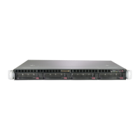
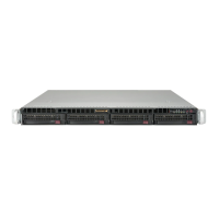
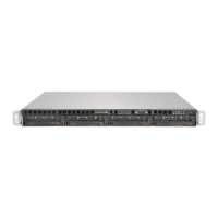
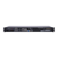
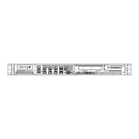
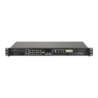
Supermicro SuperServer 5019C-MHN2 - Front Control Panel

Supermicro SuperServer 5019C-MHN2
139 pages
To Next Page IconTo Next Page
To Previous Page IconTo Previous Page
Loading...
46
SuperServer 5019C-MHN2 User's Manual
Power Button
UID LED
NIC1 Active LED
Reset Button
HDD LED
PWR LED
Reset
PWR
3.3V Stby
3.3V Stby
Ground
19
X
Ground
X
3.3V Stby
20
1 2
Ground
Power Fail LED
NIC2 Active LED
NMI
3.3V
OH/Fan Fail LED
3.3V Stby
Figure 4-1. JF1 Header Pins
4.3 Front Control Panel
JF1 contains header pins for various buttons and indicators that are normally located on a


buttons and LED indicators.
Power Button
The Power Button connection is located on pins 1 and 2 of JF1. Momentarily contacting both
󰀨
           󰀨    

Power Button
Pin Denitions (JF1)
Pins Denition
1 Signal
2 Ground
Reset Button
The Reset Button connection is located on pins 3 and 4 of JF1. Attach it to a hardware reset

Reset Button
Pin Denitions (JF1)
Pins Denition
3 Reset
4 Ground

Table of Contents

Related product manuals