6-2
SUPERSERVER 6028U-T Series User's Manual
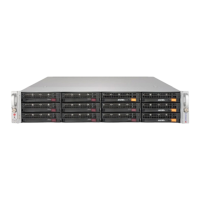
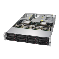
Figure 6-1. Chassis Front and Rear Views
6-2 Control Panel
The control panel (located on the front of the chassis) must be connected to the JF1
connector on the serverboard to provide you with system status indicators. These
wires have been bundled together as a ribbon cable to simplify the connection.
Connect the cable from JF1 on the serverboard to the appropriate header on the
Control Panel printed circuit board. Make sure the red wire plugs into pin 1 on both
connectors.
The control panel LEDs inform you of system status. See "Chapter 3: System
Interface" for details. Details on the JF1 header can be found in "Chapter 5:
Advanced Serverboard Setup."
Logical Drive Conguration
HDD2 HDD5 HDD/NVMe HDD/NVMe
HDD1 HDD4 HDD7 HDD/NVMe
HDD0 HDD3 HDD6 HDD/NVMe
Control Panel
Hard Drive Bays (12)
PCI Expansion Slots (with riser cards)
I/O Ports
Power Supplies
LAN Ports
(2 or 4, depending
on server model)
PWS1 PWS2
 Loading...