5-20
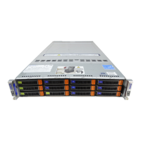
SUPERSERVER 6048R-TXR User's Manual
Powered SATA DOM Connectors
Two powered SATA DOM (Device-
on-Module) devices with power
connections are located at JSD1/
JSD2.These connectors provide
backward-compatible power support
to non-Supermicro SATA DOMs that
require external power.
JSD1/JSD2
Pin Denitions
Pin# Denition
1 +5V
2 Ground
3 Ground
I-SGPIO1/2 & S-SGPIO1 Headers
Three SGPIO (Serial-Link General
Purpose Input/Output) headers are
provided. I-SGPIO1/2 supports the
I-SATA 0-5 ports and S-SGPIO
supports the S-SATA 0-3 ports. See the
tables on the right for more information.
I-SGPIO1/2 & S-SGPIO1 Headers
Pin Denitions
Pin# Denition Pin Denition
1 NC 2 NC
3 Ground 4 Data
5 Load 6 Ground
7 Clock 8 NC
Power SMB (I
2
C) Connector
The Power System Management Bus
(I
2
C) connector (JPI
2
C1) monitors the
power supply fan and power supply
temperatures. See the table on the
right for pin denitions.
PWR SMB
Pin Denitions
Pin# Denition
1 Clock
2 Data
3 PMBUS_Alert
4 Ground
5 +3.3V
Standby Power Header
The +5V Standby Power header is
located at JSTBY1. See the table
on the right for pin denitions. (You
must also have a card with a Standby
Power connector and a cable to use
this feature.)
Standby PWR
Pin Denitions
Pin# Denition
1 +5V Standby
2 Ground
3 No Connection
NC = No Connection
 Loading...