26
SuperServer E302-9A User's Manual
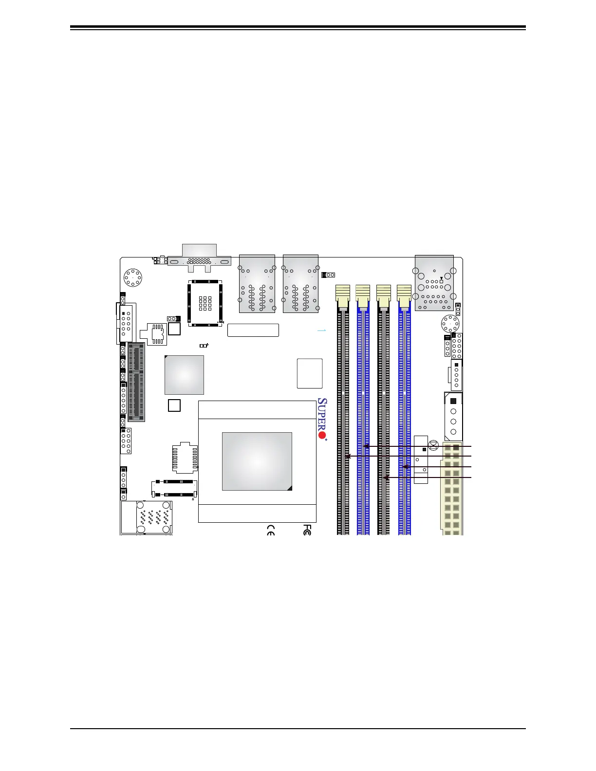
Figure 3-2. DIMM Slots
BIOS LICENSE
JPW1
A2SDi-2C-HLN4F
REV:1.00
DESIGNED IN USA
BAR CODE
COM1
JPCIE1
SRW1
SRW2
JUIDB
JPL1
JWD1
JPG1
JBR1
JPME2
JI2C1 JI2C2
PRESS FIT
JSAS2
JMD1
JB3
JD1
JSMB1
JGP1
1
JBT1
JPH1
JL1
JRT4
JRT3
I-SATA2
I-SATA1 I-SATA3
I-SATA0
JUSB3A1
UIDLED1
A
LEDM1
FANA
FAN3
SUPERDOM
SATA DOM+POWER
8-11
I-SATA
IPMI LAN
DIMMA1
DIMMA2
DIMMB2
DIMMB1
CPU
ALWAYS POPULATE DIMMA1 FIRST
CPU SLOT7 PCI-E 3.0 X4
M.2:PCI-E 3.0 X2 / I-SATA
LAN4
INTRUSION
JD1:
1-4:SPEAKER
CHASSIS
JL1:
JPB1:BMC
1-2:ENABLE
2-3:DISABLE
1-2:ENABLE
JI2C1:
2-3:DISABLE
JI2C2:
1-2:ENABLE
2-3:DISABLE
1-2:NORMAL
JPME2:
2-3:ME MANUFACTURING MODE
2-3:NMI
1-2:RST
JWD1:WATCH DOG
JPI2C1
JBR1
1-2:NORMAL
2-3:BIOS RECOVERY
LAN2
USB0/1
USB2/3
VGA
LAN1
LAN3
BT1
DIMM Module Population Sequence
When installing memory modules, the DIMM slots should be populated in the following order:
DIMMB1, DIMMA1, DIMME1, DIMMD1.
• Always use DDR4 DIMM modules of the same type, size, and speed.
• Mixed DIMM speeds can be installed. However, all DIMMs will run at the speed of the
slowest DIMM.
• The motherboard will support odd-numbered modules (one or three modules installed).
However, for best memory performance, install DIMM modules in pairs to activate memory
interleaving.
DIMMA1
DIMMB2
DIMMA2
DIMMB1