33
Chapter 4: Motherboard Connections
Chapter 4
Motherboard Connections
LEDs on the motherboard are also described here. A serverboard layout indicating component
locations may be found in Chapter 1.
Please review the Safety Precautions in Appendix B before installing or removing components.
4.1 Power Connections
Two power connections on the 7049GP-TRT must be connected to the power supply. The
wiring is included with the power supply.
• 24-pin Primary ATX Power (JPWR1)
• 8-pin Processor Power (JPWR2)
Warning: To provide adequate power to your system and to avoid damaging the power sup-
ply or the motherboard, be sure to connect all power connectors mentioned above to the
power supply. Failure in doing so may void the manufacturer warranty on your power supply
and motherboard.
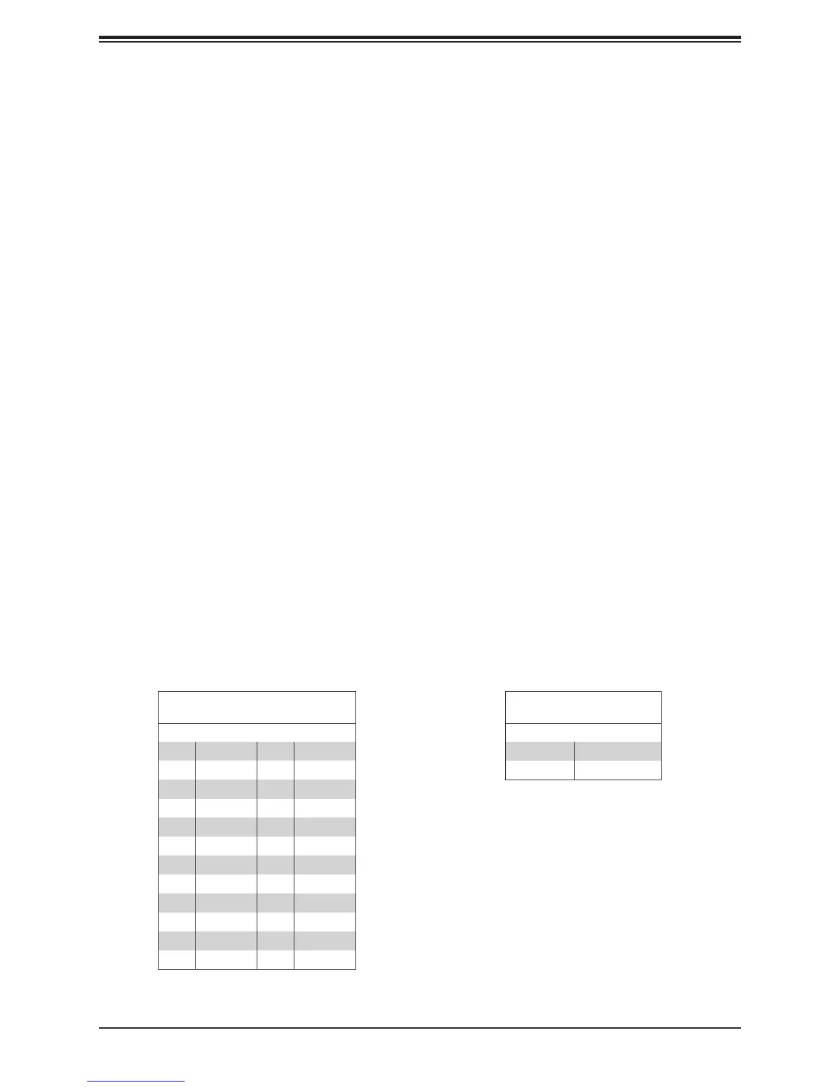
Main ATX Power Supply Connector
ATX Power 24-pin Connector
Pin Denitions
Pin# Denition Pin# Denition
13 +3.3V 1 +3.3V
14 NC 2 +3.3V
15 Ground 3 Ground
16 PS_ON 4 +5V
17 Ground 5 Ground
18 Ground 6 +5V
19 Ground 7 Ground
20 Res (NC) 8 PWR_OK
21 +5V 9 5VSB
22 +5V 10 +12V
23 +5V 11 +12V
24 Ground 12 +3.3V
12V 8-pin PWR Connector
Pin Denitions
Pins Denition
1 through 4 Ground
5 through 8 +12V

 Loading...