EasyManua.ls Logo

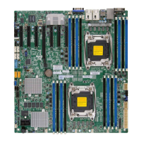
Supermicro X10DRL-CT - Connecting Cables; Power Connectors

Supermicro X10DRL-CT
119 pages
To Next Page IconTo Next Page
To Previous Page IconTo Previous Page
Loading...
Chapter 2: Installation
2-25
SAN MAC
BIOS LICENSE
SAS CODE
MAC CODE
IPMI CODE
BAR CODE
UID
LEDPWR
LEDBMC
JUSBRJ45
FAN6
FAN5
FAN1
FANB
FAN2
FAN3
FAN4
FANA
JIPMB1
JNVI2C1
JVRM2
JPTG1
1
JPB1
3
JPF1
JPF2
JPG1
JBR1
JPME2
JI2C1
JI2C2
JPS1
JPL2
JPL1
JVRM1
JWD1
J24
1
13
1224
1
J7J5
JS18
JF1
JPWR2
JPWR1
1
JL1
J21
JPI2C1
24
JPS7
SP1
BT1
+
JLAN3
JUIDB1
JSD1
JS1
JSTBY1
I-SGPIO1
I-SGPIO2
J25
JTPM1
JVGA
JLAN1
JBT1
I2C BUS FOR PCI-E SLOT
1-2:ENABLE
2-3:DISABLE
X10DRL-CT
DESIGNED IN USA
REV:1.00
CHASSIS INTRUSION
JL1
2-3:DISABLE
1-2:ENABLE
JI2C1/JI2C2
1-2:NORMAL
2-3:BIOS RECOVERY
JBR1
2-3:ME MANUFACTURING MODE
JPME2
1-2:NORMAL
1-2 ENABLE
JPL2 LAN
2-3 DISABLE
JPL1/
JPI2C1:PWR I2C
JPG1:VGA
JPB1:BMC
2-3 DISABLE
1-2 ENABLE
2-3 DISABLE
1-2 ENABLE
JPTG1:10Gb LAN
2-3 DISABLE
1-2 ENABLE
JPS1:SAS
L-SAS0-3
L-SAS4-7
USB8/9(3.0)
PCI-E 3.0 X8
LAN4
LAN3
LAN1
USB12/13(3.0)
I-SATA0
I-SATA1
I-SATA2
I-SATA3
USB2/3
USB4
JTPM1:TPM/PORT80
CHASSIS INTRUSION
I-SATA4
CMOS CLEAR
I-SATA5
CPU2 SLOT4
SPEAKER-PIN 4-7
JD1:
PWR LED-PIN 1-3
2-3:NMI
JWD1:WATCH DOG
1-2:RST
CPU1 SLOT5 PCI-E 3.0 X16
CPU1 SLOT6 PCI-E 3.0 X8
RSTPWR
ON
JF1
P1-DIMMD1
P1-DIMMC1
X NICOH/
2FF
HDDNIC
LED1
PWR
LED
NMIX
P2-DIMMF1
P2-DIMME1
CPU2
VGA
CPU1
P1-DIMMB1
P1-DIMMA1
P2-DIMMH1
P2-DIMMG1
COM1
IPMI_LAN
LAN2
JD1
Warning: To provide adequate power supply
to the motherboard, be sure to connect the
24-pin ATX PWR (J24), and the two 8-pin
PWR connectors (JPWR1, JPWR2) to the
power supply. Failure to do so may void the
manufacturer warranty on your power supply
and motherboard.
2-7 Connecting Cables
Power Connectors
A 24-pin main power supply connector
(J24), and two 8-pin CPU power connec-
tors (JPWR1/JPWR2) are located on the
motherboard. These power connectors
meet the SSI EPS 12V specication and
must be connected to your power supply
to provide adequate power to the system.
See the tables on the right for pin deni-
tions.
A. J24: 24-pin ATX PWR
(Req'd)
B. JPWR1: 8-pin Proces-
sor PWR (Req'd)
C. JPWR2: 8-pin Proces-
sor PWR (Req'd)
A
B
C
ATX Power 24-pin Connector
Pin Denitions (J24)
Pin# Denition Pin # Denition
13 +3.3V 1 +3.3V
14 -12V (NC) 2 +3.3V
15 GND 3 GND
16 PS_ON 4 +5V
17 GND 5 GND
18 GND 6 +5V
19 GND 7 GND
20 Res (NC) 8 PWR_OK
21 +5V 9 5VSB
22 +5V 10 +12V
23 +5V 11 +12V
24 GND 12 +3.3V
(Required)
12V 8-pin Power Connec-
tor Pin Denitions
Pins Denition
1 through 4 Ground
5 through 8 +12V
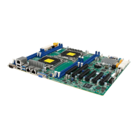
Table of Contents

Related product manuals