42
Super X11DPH-i/X11DPH-T/X11DPH-Tq User's Manual
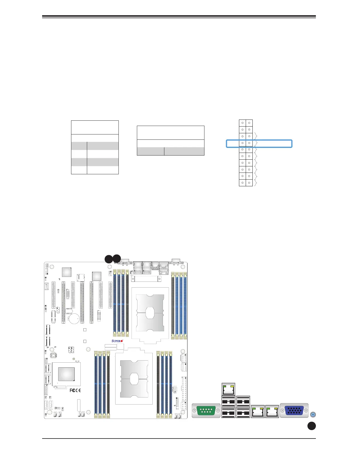
Power Button
UID LED
NIC1 Active LED
Reset Button
HDD LED
PWR LED
3.3V Stby
3.3V Stby
Ground
19
X
Ground
X
3.3V Stby
20
12
Ground
Power Fail LED
NIC2 Active LED
NMI
3.3V
3.3V
OH/PWR/Fail/Fan Fail LED
IPMI CODE
+
BIOS LICENSE
MAC CODE
X11DPH-i
REV: 1.10
BAR CODE
LEDM1
JUIDB1
JHSSI
JPWR4
JPWR2
JPWR1
JSD1
JSD2
JSDCARD1
SATA2
SATA1
MH4
MH11
T-SGPIO1
JNCSI
JRK1
JTPM1
JPWR3
JF1
JD1
JL1
JSTBY1
BT1
JPME2
JWD1
JIPMB1
LE1
LE4
LE3
JBT1
FAN6
FAN5
FANB
FANA
FAN4 FA N3
FAN2
FAN1
ASPEED
AST2500
LAN
CTRL
Intel
PCH
LE2
P2-DIMMF1
P2-DIMME1
P2-DIMMD1
P2-DIMMD2
P1-DIMMC1
P1-DIMMB1
P1-DIMMA1
P1-DIMMA2
P2-DIMMA2
P2-DIMMA1
P2-DIMMB1
P2-DIMMC1
P1-DIMMD2
P1-DIMMD1
P1-DIMME1
P1-DIMMF1
Battery
BMC
BIOS
M.2-C2
M.2-C1
CPU1-HSSI GPIO
USB 4/5(3.0)
USB 6 (3.0)
S-SATA1
S-SATA0
I- SATA 4~ 7
I- SATA 0~ 3
CPU1 SLOT1 PCI-E 3.0 x8
CPU2 SLOT2 PCI-E 3.0 x16
CPU1 SLOT3 PCI-E 3.0 x8
CPU2 SLOT4 PCI-E 3.0 x16
CPU2 SLOT5 PCI-E 3.0 x16
CPU1 SLOT6 PCI-E 3.0 x8
CPU1 SLOT7 PCI-E 3.0 x8
VGA
LAN2
LAN1
USB 2/3(3.0)
USB 0/1(3.0)
IPMI_LAN
COM1
JP4
CPU2
CPU1
1
1
2
1. UID
2. UID LED
Unit Identifi er Switch/UID LED Indicator
A Unit Identifi er (UID) switch and a rear UID LED (LE1) are located on the I/O back panel.
A front UID switch is located on pins 7 & 8 of the front panel control (JF1). When you press
the front or the rear UID switch, both front and rear UID LEDs will be turned on. Press the
UID switch again to turn off the LED indicators. The UID indicators provide easy identifi cation
of a system that may be in need of service. (Note: UID can also be triggered via IPMI on
the motherboard. For more information, please refer to the IPMI User's Guide posted on our
website at http://www.supermicro.com.)
UID Switch
Pin Defi nitions
Pin# Defi nition
1 Ground
2 Ground
3 Button In
4 Button In
UID LED
Pin Defi nitions
Color Status
Blue: On Unit Identifi ed
 Loading...


