62
Super X11DPH-i/X11DPH-T/X11DPH-Tq User's Manual
IPMI CODE
+
BIOS LICENSE
MAC CODE
X11DPH-i
REV: 1.10
BAR CODE
LEDM1
JUIDB1
JHSSI
JPWR4
JPWR2
JPWR1
JSD1
JSD2
JSDCARD1
SATA2
SATA1
MH4
MH11
T-SGPIO1
JNCSI
JRK1
JTPM1
JPWR3
JPI2C1
JF1
JD1
JL1
JSTBY1
BT1
JPME2
JWD1
JIPMB1
LE1
LE4
LE3
JBT1
FAN6
FAN5
FANB
FANA
FAN4 FA N3
FAN2
FAN1
ASPEED
AST2500
LAN
CTRL
Intel
PCH
LE2
P2-DIMMF1
P2-DIMME1
P2-DIMMD1
P2-DIMMD2
P1-DIMMC1
P1-DIMMB1
P1-DIMMA1
P1-DIMMA2
P2-DIMMA2
P2-DIMMA1
P2-DIMMB1
P2-DIMMC1
P1-DIMMD2
P1-DIMMD1
P1-DIMME1
P1-DIMMF1
Battery
BMC
BIOS
M.2-C2
M.2-C1
CPU1-HSSI GPIO
USB 4/5(3.0)
USB 6 (3.0)
S-SATA1
S-SATA0
I- SATA 4~ 7
I- SATA 0~ 3
CPU1 SLOT1 PCI-E 3.0 x8
CPU2 SLOT2 PCI-E 3.0 x16
CPU1 SLOT3 PCI-E 3.0 x8
CPU2 SLOT4 PCI-E 3.0 x16
CPU2 SLOT5 PCI-E 3.0 x16
CPU1 SLOT6 PCI-E 3.0 x8
CPU1 SLOT7 PCI-E 3.0 x8
VGA
LAN2
LAN1
USB 2/3(3.0)
USB 0/1(3.0)
IPMI_LAN
COM1
JP4
CPU2
CPU1
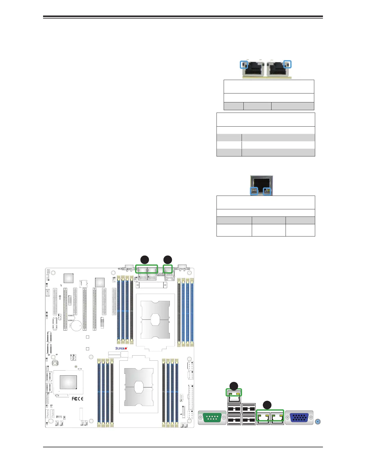
2.9 LED Indicators
1. LAN1/LAN2 LEDs
2. IPMI LAN LEDs
1
1
LAN Link Indicator
LED Settings
LED Color Defi nition
Off No Connection, 10 or 100 Mbps
Green 10 Gbps (X11DPH-T/Tq Only)
Amber 1 Gbps
IPMI-Dedicated LAN LEDs
In addition to LAN 1/LAN 2, an IPMI-
dedicated LAN is located on the I/O
Backplane of the motherboard. The amber
LED on the right indicates activity, while
the LED on the left indicates the speed of
the connection. See the tables at right for
more information.
IPMI LAN Link LED (Left) &
Activity LED (Right)
Color State Defi nition
Link (Left) Green: Solid 100 Mbps
Activity (Right) Amber:
Blinking
Active
LAN LEDs
The LAN ports are located on the IO
Backplane on the motherboard. Each
Ethernet LAN port has two LEDs. The
yellow LED indicates activity. Link LED,
located on the left side of the LAN port,
may be green, amber or off, indicating the
speed of the connection. See the tables at
right for more information.
GLAN Activity Indicator (Left)
LED Settings
Color State Defi nition
Yellow Flashing Active
LAN 1/2
Link LED
Activity LED
IPMI LAN
Link LED
Activity LED
2
2
 Loading...


