59
Chapter 2: Installation
IPMI CODE
+
BIOS LICENSE
MAC CODE
X11DPH-i
REV: 1.10
BAR CODE
LEDM1
JUIDB1
JHSSI
JPWR4
JPWR2
JPWR1
JSD1
JSD2
JSDCARD1
SATA2
SATA1
MH4
MH11
T-SGPIO1
JNCSI
JRK1
JTPM1
JPWR3
JF1
JD1
JL1
JSTBY1
BT1
JPME2
JWD1
JIPMB1
LE1
LE4
LE3
JBT1
FAN6
FAN5
FANB
FANA
FAN4 FA N3
FAN2
FAN1
ASPEED
AST2500
LAN
CTRL
Intel
PCH
LE2
P2-DIMMF1
P2-DIMME1
P2-DIMMD1
P2-DIMMD2
P1-DIMMC1
P1-DIMMB1
P1-DIMMA1
P1-DIMMA2
P2-DIMMA2
P2-DIMMA1
P2-DIMMB1
P2-DIMMC1
P1-DIMMD2
P1-DIMMD1
P1-DIMME1
P1-DIMMF1
Battery
BMC
BIOS
M.2-C2
M.2-C1
CPU1-HSSI GPIO
USB 4/5(3.0)
USB 6 (3.0)
S-SATA1
S-SATA0
I- SATA 4~ 7
I- SATA 0~ 3
CPU1 SLOT1 PCI-E 3.0 x8
CPU2 SLOT2 PCI-E 3.0 x16
CPU1 SLOT3 PCI-E 3.0 x8
CPU2 SLOT4 PCI-E 3.0 x16
CPU2 SLOT5 PCI-E 3.0 x16
CPU1 SLOT6 PCI-E 3.0 x8
CPU1 SLOT7 PCI-E 3.0 x8
VGA
LAN2
LAN1
USB 2/3(3.0)
USB 0/1(3.0)
IPMI_LAN
COM1
JP4
CPU2
CPU1
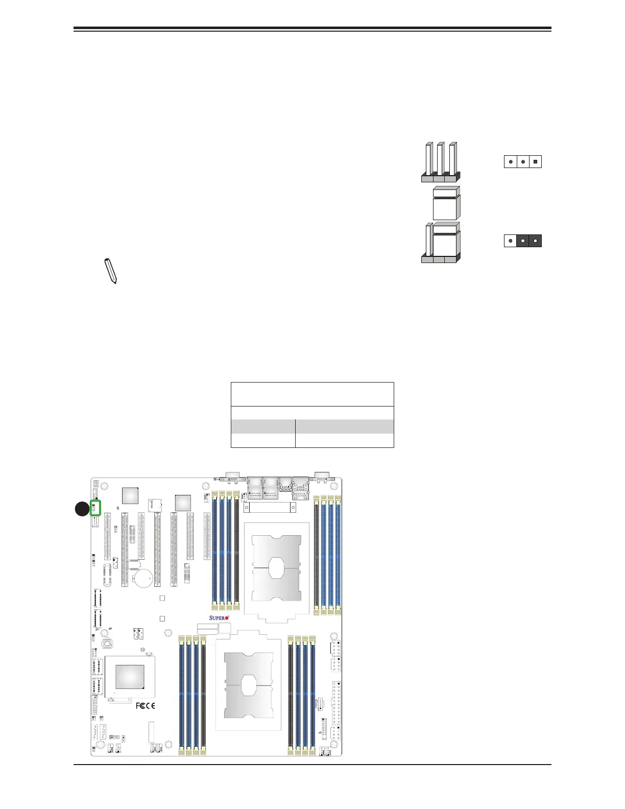
2.8 Jumper Settings
How Jumpers Work
To modify the operation of the motherboard, jumpers can be
used to choose between optional settings. Jumpers create
shorts between two pins to change the function of the connector.
Pin 1 is identifi ed with a square solder pad on the printed circuit
board. See the diagram at right for an example of jumping
pins 1 and 2. Refer to the motherboard layout page for jumper
locations.
Note: On two-pin jumpers, "Closed" means the jumper is
on and "Open" means the jumper is off the pins.
Connector
Pins
Jumper
Setting
3 2 1
3 2 1
Manufacturing Mode Select
Close JPME2 to bypass SPI fl ash security and force the system to use Manufacturing Mode,
which will allow you to fl ash the system fi rmware from a host server to modify system settings.
See the table below for jumper settings.
Manufacturing Mode Select
Jumper Settings
Jumper Setting Defi nition
Pins 1-2 Normal (Default)
Pins 2-3 Manufacturing Mode
1
1. Manufacturing Mode Select
 Loading...


