55
Chapter 2: Installation
IPMI CODE
+
BIOS LICENSE
MAC CODE
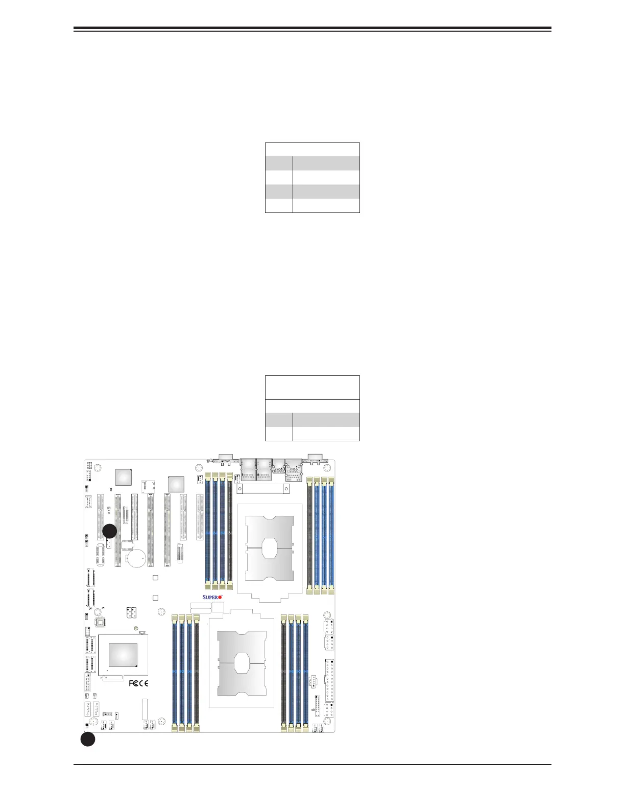
X11DPH-i
REV: 1.10
BAR CODE
LEDM1
JUIDB1
JHSSI
JPWR4
JPWR2
JPWR1
JSD1
JSD2
JSDCARD1
SATA2
SATA1
MH4
MH11
T-SGPIO1
JNCSI
JRK1
JTPM1
JPWR3
JF1
JD1
JL1
JSTBY1
BT1
JPME2
JWD1
JIPMB1
LE1
LE4
LE3
JBT1
FAN6
FAN5
FANB
FANA
FAN4 FA N3
FAN2
FAN1
ASPEED
AST2500
LAN
CTRL
Intel
PCH
LE2
P2-DIMMF1
P2-DIMME1
P2-DIMMD1
P2-DIMMD2
P1-DIMMC1
P1-DIMMB1
P1-DIMMA1
P1-DIMMA2
P2-DIMMA2
P2-DIMMA1
P2-DIMMB1
P2-DIMMC1
P1-DIMMD2
P1-DIMMD1
P1-DIMME1
P1-DIMMF1
Battery
BMC
BIOS
M.2-C2
M.2-C1
CPU1-HSSI GPIO
USB 4/5(3.0)
USB 6 (3.0)
S-SATA1
S-SATA0
I- SATA 4~ 7
I- SATA 0~ 3
CPU1 SLOT1 PCI-E 3.0 x8
CPU2 SLOT2 PCI-E 3.0 x16
CPU1 SLOT3 PCI-E 3.0 x8
CPU2 SLOT4 PCI-E 3.0 x16
CPU2 SLOT5 PCI-E 3.0 x16
CPU1 SLOT6 PCI-E 3.0 x8
CPU1 SLOT7 PCI-E 3.0 x8
VGA
LAN2
LAN1
USB 2/3(3.0)
USB 0/1(3.0)
IPMI_LAN
COM1
JP4
CPU2
CPU1
Chassis Intrusion (Available when an Optional External Speaker is Installed)
A Chassis Intrusion header is located at JL1 on the motherboard. Connect an appropriate
cable from JL1 to the chassis so that you can be informed of a chassis intrusion when the
system case is opened. Please note that this feature will work properly when an optional
external speaker is connected to the onboard speaker header located at JD1. Refer to the
table below for pin defi nitions.
Chassis Intrusion
Pin Defi nitions
Pin# Defi nition
1 Intrusion Input
2 Ground
1. BMC External I
2
C Header
2. Chassis Intrusion (external
speaker is required)
1
4-pin BMC External I
2
C Header
A System Management Bus header for IPMI 2.0 is located at JIPMB1. Connect the appropriate
cable here to use the IPMB I
2
C connection on your system. Refer to the table below for pin
defi nitions.
Pin# Defi nition
1 Data
2 Ground
3 Clock
4 No Connection
2
 Loading...


