61
Chapter 2: Installation
PSU2
PSU1
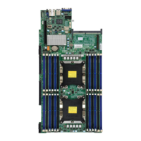
X11DPU
DESIGNED IN USA
BAR CODE
IPMI CODE
CPU2
CPU1
BIOS
LICENSE
COM1
LAN
CTRL
LED_P1_D2
LED_P1_D1
LED_P1_E2
LED_P1_E1
LED_P1_F2
LED_P1_F1
LED_P1_A2
LED_P1_A1
LED_P1_C2
LED_P1_B1
LED_P1_B2
LED_P1_C1
LED_P2_F2
LED_P2_F1
LED_P2_E2
LED_P2_E1
LED_P2_D2
LED_P2_D1
LED_P2_C2
LED_P2_C1
LED_P2_B2
LED_P2_B1
LED_P2_A2
LED_P2_A1
JRK1
S-UM12
JVGA2
BT1
JBT1
JL1
JUIDB2
JF1
JPG1
JVRM1
JWD1
FAN8
FAN7
FAN6
FAN5
FAN4
FAN3
FAN2
FAN1
JIPMB1
JNVI2C1
JNVI2C2
SP1
JSD1JSD2
T-SGPIO3
LED1
LEDM1
LEDPWR
JVRM2
JTPM1
SXB3B
SXB1B
SXB2
FAIL
LED
UID NIC
2 1
NIC
LED
HDD PWR
LED
X NMI
PWR
ON
JF1
RST
PS
P2_NVMe1
P2_NVMe0
P2-DIMMF2
P2-DIMMF1
P2-DIMME1
P2-DIMME2
SXB1A
CPU2_PORT3A
CPU2_PORT2C CPU2_PORT2A
SXB1C
P2-DIMMD2
P2-DIMMD1
CPU2_PORT1A
PCH_PORT1 CPU2_DMI
USB3/4 (3.0)
S-SATA0~3
S-SATA4
P2-DIMMA2
S-SATA5
P2-DIMMA1
UID
P2-DIMMB2
P2-DIMMB1
P2-DIMMC2
I-SATA0~3
P2-DIMMC1
I-SATA4~7
GPU PWR2
USB2 (3.0)
P1-DIMMF2
SXB3C
P1-DIMMF1
CPU1_PORT1A
SXB3A
CPU1_PORT3A
CPU1_PORT3C CPU1_PORT2A
CPU1_PORT2C
P1-DIMMD1
P1-DIMME1
P1-DIMME2
P1-DIMMD2
P1-DIMMA2
P1-DIMMA1
P1-DIMMC1
P1-DIMMC2
P1-DIMMB2
P1-DIMMB1
P1_NVMe0 P1_NVMe1
BP PWR4
VGA
IPMI_LAN
USB0/1
(3.0)
BMC
JSDCARD1
PCH
GPU PWR3
GPU PWR4
GPU PWR1
BP PWR2 BP PWR1
BP PWR3
CPU2_PORT3C
JPB1
REV:1.10
JHFI2
JHFI1
2.9 LED Indicators
IPMI-Dedicated LAN LEDs
A dedicated IPMI LAN is also included on the motherboard. The amber LED on the right of
the IPMI LAN port indicates activity, while the green LED on the left indicates the speed of
the connection. See the table below for more information.
IPMI LAN LEDs
Color Status Denition
Off Off
No
Connection
Green:
Solid
Link/Speed
(Left)
100 Mb/s
Amber
Blinking
Activity
(Right)
Active
IPMI LAN
Activity LEDLink LED
LAN 1/LAN 2
IPMI LAN
(X8ST3-F)
1
1. IPMI-Dedicated LAN LED
2. UID LED
1
UID LED
LED Indicator
LED Color Denition
Blue: On Unit Identied
Unit ID LED
A rear UID LED indicator at LED1 is located near the UID switch on the I/O back panel. This
UID indicator provides easy identication of a system unit that may need service.
2
 Loading...

