11
Chapter 1: Introduction
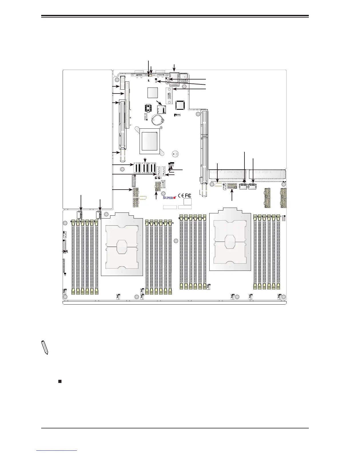
Quick Reference
Notes:
• See Chapter 2 for detailed information on jumpers, I/O ports, and JF1 front panel con-
nections.
• " " indicates the location of Pin 1.
• Components/jumpers/LED indicators not documented are reserved for internal testing only.
• Use only the correct type of onboard CMOS battery as specied by the manufacturer. Do
not install the onboard battery upside down to avoid possible explosion.
X11DPU
DESIGNED IN USA
BAR CODE
IPMI CODE
CPU2
CPU1
BIOS
LICENSE
FAIL
LED
UID NIC
2 1
NIC
LED
HDD PWR
LED
X NMI
PWR
ON
JF1
RST
PS
CPU2_PORT3A
CPU2_PORT2C CPU2_PORT2A
CPU2_PORT1A
PCH_PORT1 CPU2_DMI
CPU1_PORT1A
CPU1_PORT3A
CPU1_PORT3C CPU1_PORT2A
CPU1_PORT2C
CPU2_PORT3C
REV:1.10
FAN1FAN2
FAN3FAN5
FAN6
FAN7FAN8
FAN4
JL1
JF1
LEDPWR
JNVI2C2
T-SGPIO3
BP PWR2
BP PWR4
BP PWR3
BP PWR1
PSU1PSU2
P1_NVMe1
P1_NVMe0
JNVI2C1
GPU PWR1
SXB3A
SXB3B
SXB3C
SP1
BT1
JBT1
JRK1
JWD1
JVRM1
SXB1C
SXB1B
SXB1A
SXB2
GPU PWR2
GPU PWR4
GPU PWR3
JSD1
JSD2
USB2
USB3/4
USB0/1
IPMI_LAN
JVGA2
JIPMB1
COM1
JPG1
P2_NVMe1
P2_NVMe0
UID
JSDCARD1
LEDM1
LED1
VGA
S-SATA5
S-SATA4
S-SATA0~3
I-SATA0~3
I-SATA4~7
P1-DIMMB1
P1-DIMMB2
P1-DIMMA1
P1-DIMMA2
P1-DIMMC1
P1-DIMMC2
LED_P1_B1
LED_P1_B2
LED_P1_A1
LED_P1_A2
LED_P1_C1
LED_P1_C2
LED_P1_E2
LED_P1_E1
LED_P1_F2
LED_P1_F1
LED_P1_D2
LED_P1_D1
LED_P2_E2
LED_P2_E1
LED_P2_F2
LED_P2_F1
LED_P2_D2
LED_P2_D1
LED_P2_B2
LED_P2_B1
LED_P2_C2
LED_P2_C1
LED_P2_A2
LED_P2_A1
P1-DIMME2
P1-DIMME1
P1-DIMMF2
P1-DIMMF1
P1-DIMMD2
P1-DIMMD1
P2-DIMMB1
P2-DIMMB2
P2-DIMMA1
P2-DIMMA2
P2-DIMMC1
P2-DIMMC2
P2-DIMME2
P2-DIMME1
P2-DIMMF2
P2-DIMMF1
P2-DIMMD2
P2-DIMMD1
JTPM1
JVRM2
JHFI1
JHFI2

 Loading...


