31
Chapter 2: Installation
C
A
PRESS FIT
A
BAR CODE
REV:1.01
X12STL-IF
DESIGNED IN USA
BIOS LICENSE
JD1
MH4
MH2
JPL1
JL1
JPME2
I-SATA5
JSD1
I-SATA4
BT1
JSMB1
JPV1
MH1
FAN1
FAN2
JPWR1
MH3
JF1
JPI2C1
FAN3
JUIDB1
JMD1_SRW1
JTPM1
LED1
JBT1
JMD1
JPCIE1
JRF1
FANA
JPG1
JCPLD1
JVRM1
JPL2
JWD1
LED3
LED2
LEDM1
CPU
DIMMB1
CPU SLOT7 PCI-E 4.0 X16
DIMMA1
OH
NIC1
VGA
X
PWR
HDD
LED
PWR
LED
RST
FF
I-SATA0-3
LAN1/2
JF1:
NIC2
ON
USB 6/7(3.2)
USB 2/3
COM
USB 0/1
USB 4/5(3.2)
BMC_LAN
UID
JSD2
1
2
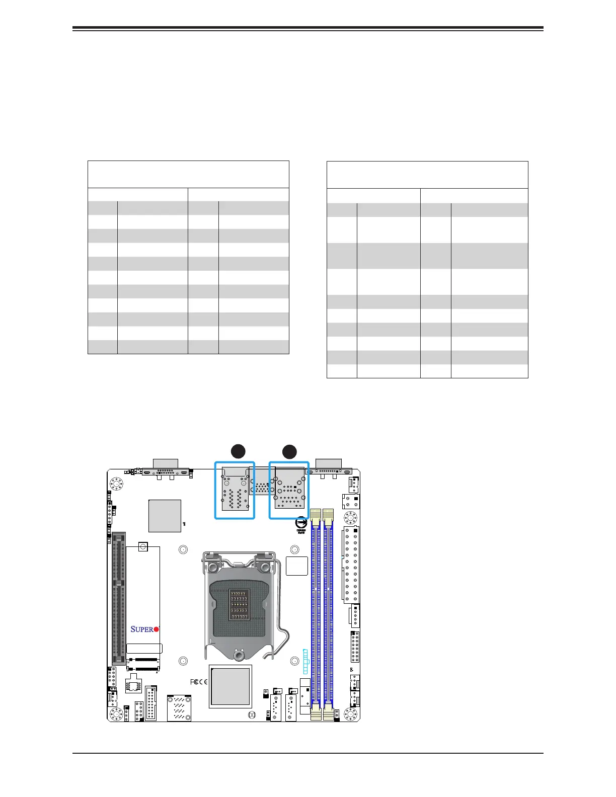
1. LAN1/2
2. BMC LAN
LAN Ports
Two Gigabit Ethernet ports (LAN1/2) are located on the I/O back panel. In addition to the
LAN ports, a dedicated BMC LAN on the back panel. All of these ports accept RJ45 cables.
Please refer to the LED Indicator section for LAN LED information.
LAN Port
Pin Denition
Pin# Denition Pin# Denition
1 TRD1P 11 TRD4N
2 TRD1N 12 TRCT4
3 TRCT1 13 TRD5P
4 TRD2P 14 TRD5N
5 TRD2N 15 L1-GRE-
6 TRCT2 16 L1-GRE+
7 TRD3P 17 L2-YEL-
8 TRD3N 18 COMMON
9 TRCT3 19 L2-GRE-
10 TRD4P 20 CG1
21 CG2
BMC LAN
Pin Denition
Pin# Denition Pin# Denition
9 19 GND
10 TD0+ 20
Act LED
(Yellow)
11 TD0- 21
Link 100 LED
(Green)
12 TD1+ 22
Link 1000 LED
(Amber)
13 TD1- 23 SGND
14 TD2+ 24 SGND
15 TD2- 25 SGND
16 TD3+ 26 SGND
17 TD3-
18 GND

 Loading...


