Chapter 1: Introduction
1-5
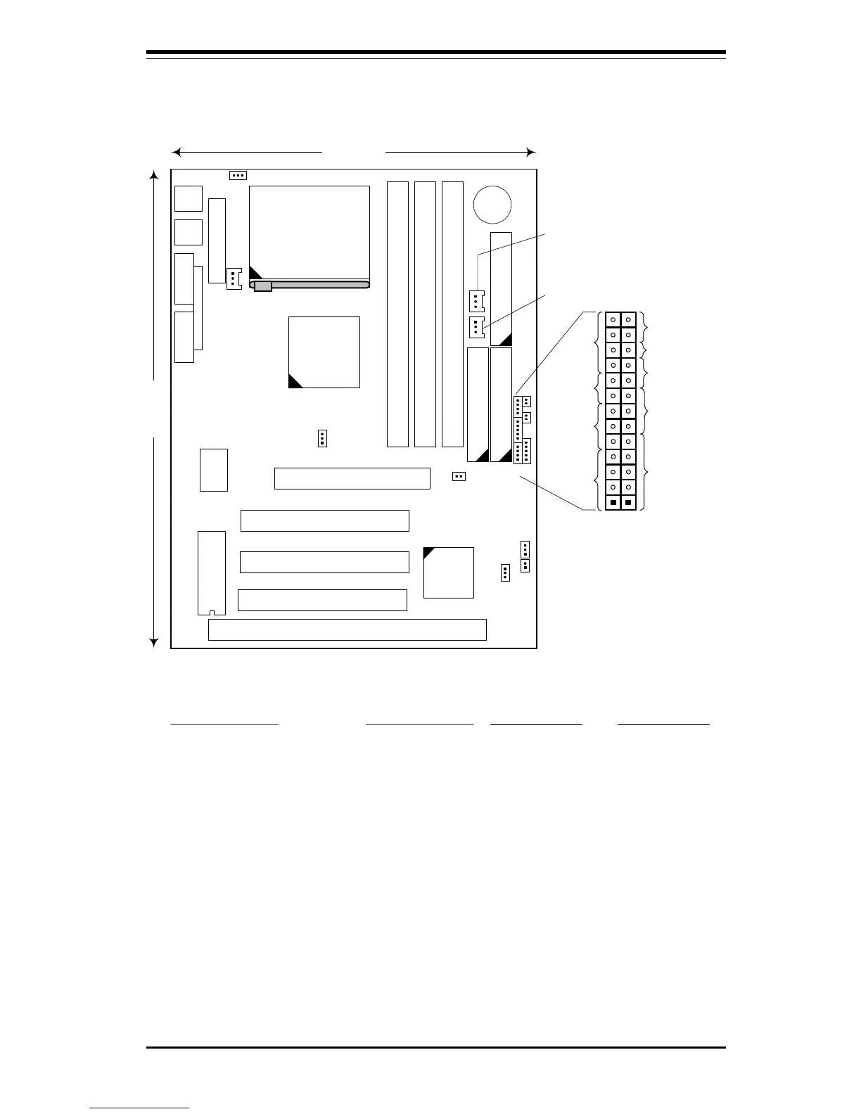
Figure 1-4. SUPER 370SBM Motherboard Layout
9.6 inches
7.25 inches
Super
l
370SBM
ISA 1
PCI 1
PCI 2
PCI 3
AGP
Super
I/O
DIMM - BANK 2
DIMM - BANK 1
DIMM - BANK 0
IDE 1
IDE 2 Floppy
Battery
1
1 1
440BX
Chipset
1
PIIX4EB
1
Keybd
---------
Mouse
USB
COM 1COM 2
LPT 1
JP11
JPWAKE (see Note 1)
JT1 - CPU FAN
JL1 - CHASSIS
INTRUSION SW
JBT1 - CMOS CLEAR
JT3 - THERMAL CTL FAN
JT2 - CHASSIS FAN
Jumper Settings
JPWAKE: 1-2 Disable Keyboard Wake-Up (default)
2-3 Enable Keyboard Wake-Up (see Note 1)
JP11: 1-2 Auto Select Bus Speed
2-3 66MHz Bus Speed
OFF 100MHz Bus Speed
JBT1: 1-2 Normal
2-3 CMOS Clear
Notes
1
To enable Keyboard Wake-Up, set
JPWAKE jumper to 2-3
and
ENABLE
Keyboard Wake-Up function in
system BIOS.
2
Chassis Intrusion Switch (JL1) is
normally open. If connected to
chassis switch, removing chassis
cover causes switch input to close.
3
No CPU jumper settings are required
for the Celeron (333/366 MHz)
processor. The settings are preset
(fixed bus ratio) in the processor.
(see Note 2)
BIOS
ATX Power
Celeron
Processor
(PPGA package)
1
1
1
1
1
WOL
JF1
JF2
IDE
LED
Keylock
Speaker
IR Con
Power On
X
Reset
JF2JF1
X
Power
LED
11
JOH - OVERHEAT LED
1
 Loading...