2-4
SUPER 370SBA/370SBM/370SLA/370SLM User's Manual
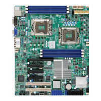
PW_ON Connector
The PW_ON connector is located on
pins 9 and 10 of JF2. Momentarily
contacting both pins will power on/off
the system. The user can also con-
figure this button to function as a
suspend button. (See BIOS setup
information on page 5-12). To turn
off the power when set to suspend
mode, hold down the power button
for at least 4 seconds. See Table 2-
4 for pin definitions.
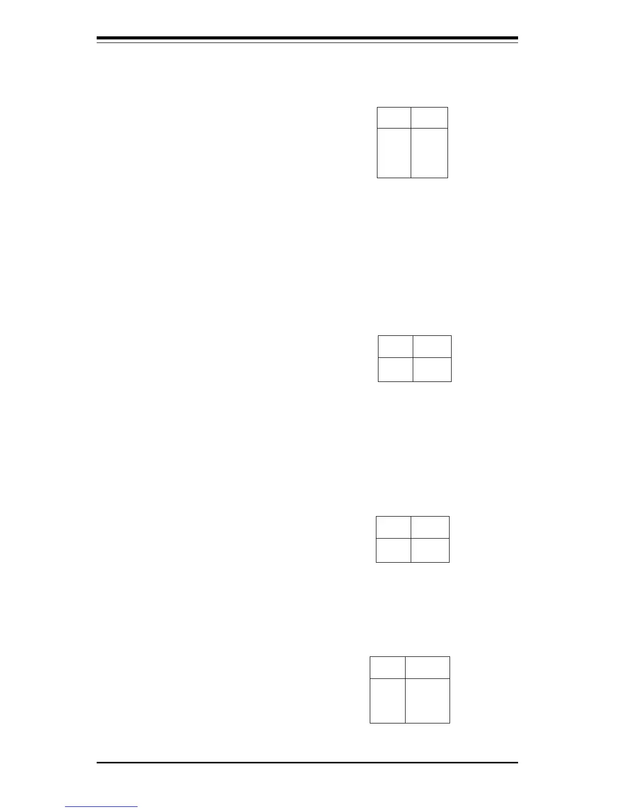
Reset Connector
The reset connector is located on
pins 12 and 13 of JF2. This con-
nector attaches to the hardware re-
set switch on the computer case.
See Table 2-5 for pin definitions.
Pin
Number
9
10
Definition
PW_ON
Ground
Table 2-4
PW-ON Connector
Pin Definitions
for JF2
Table 2-6
IDE Hard Drive LED
Pin Definitions
for JF1
Pin
Number
1
2
3
4
Definition
+5V
HD Active
HD Active
+5V
Pin
Number
12
13
Definition
Ground
Reset
Table 2-5
Reset Pin
Definitions
for JF2
Hard Drive LED Connector
The connector for the IDE hard drive
LED is located on pins 1 to 4 of JF1.
Attach the hard drive LED cable to
pins 1 and 2. See Table 2-6 for pin
definitions.
Infrared Connector
The infrared connector is located on
pins 1-5 of JF2. See Table 2-3 for pin
definitions.
Pin
Number
1
2
3
4
5
Definition
+5V
Key
IRRX
Ground
IRTX
Table 2-3
Infrared Pin
Definitions
for JF2
 Loading...