Chapter 2: Installation
2-3
2-3 Explanation and
Diagram of Jumper/
Connector
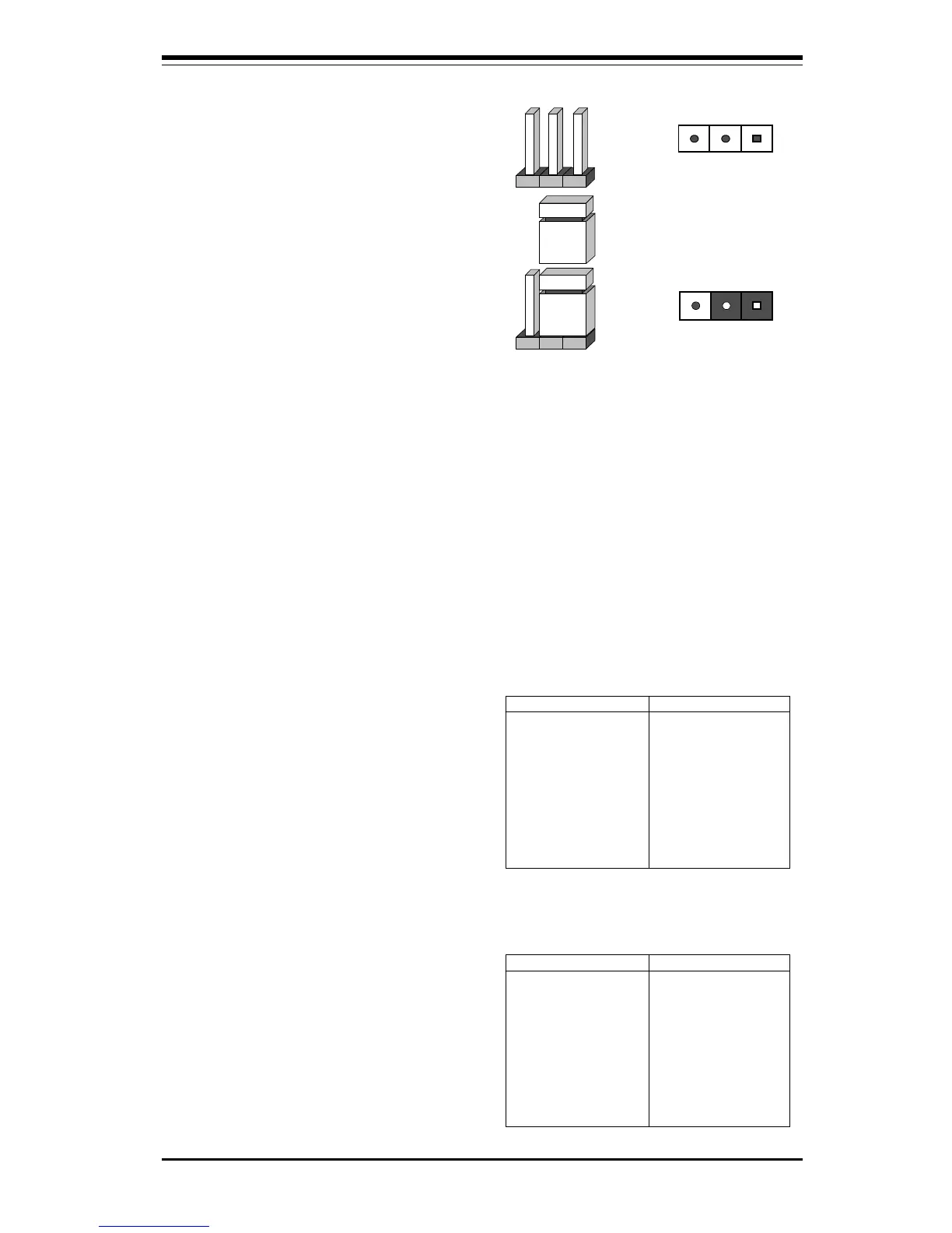
To modify the operation of the moth-
erboard, jumpers can be used to
choose between optional settings.
Jumpers create shorts between two
pins to change the function of the
connector. Pin 1 is identified with a
square.
3 2 1
Connector
Pins
Jumper
Cap
Setting
Pin 1-2 short
2-4 Mounting the Motherboard in the Chassis
All the motherboards have standard mounting holes to fit different types of
chassis. Chassis may come with a variety of mounting fasteners, made of
metal or plastic. Although a chassis may have both metal and plastic fasten-
ers, metal fasteners are the most highly recommended because they ground
the system board to the chassis. Therefore, use as many metal fasteners as
possible for better grounding.
2-5 Connecting Cables
ATX Power Supply
Connector
After you have securely mounted the
motherboard to the chassis, you are
ready to connect the cables. Attach
a power supply cable to J32 for an
ATX power supply. See Table 2-1 for
the pin definitions of an ATX power
supply.
Table 2-1
ATX Power Supply Connector
Pin Definitions for J32
Pin Number Definition
1 3.3V
2 3.3V
3 Ground
4 5V
5 Ground
6 5V
7 Ground
8 PW-OK
9 5VSB
10 12V
Pin Number Definition
11 3.3V
12 -12V
13 Ground
14 PS-ON
15 Ground
16 Ground
17 Ground
18 -5V
19 5V
20 5V
If installing a 370SBM or 370SLM
microATX motherboard, an SFX
power supply is recommended
(though an ATX power supply also
works with a microATX mother-
board). Attach a power supply cable
to J32 for an SFX power supply. See
Table 2-2 for the pin definitions of an
SFX power supply.
Table 2-2
SFX Power Supply Connector
Pin Definitions for J32
Pin Number Definition
1 3.3V
2 3.3V
3 Ground
4 5V
5 Ground
6 5V
7 Ground
8 PW-OK
9 5VSB
10 12V
Pin Number Definition
11 3.3V/sense
12 -12V
13 Ground
14 PS-ON
15 Ground
16 Ground
17 Ground
18 Reserved
19 5V
20 5V
Note: There is no -5V pin for SFX power.
 Loading...