9 Sensor installation
9 Sensor installation
Before installing the sensor, please make sure that all components listed
below are included in your package.
Qty Description Item no.
1 Sensor S695 4100
S695 4101
S695 4102
S695 4103
1 Sealing ring NA
1 Alignment key NA
2 Depending on orders:
M12 plug or M12 cable
Plug: C219 0059
Cable: A553 0104/A553 0105/A553 0146
1 Instruction manual NA
1 Calibration certificate NA
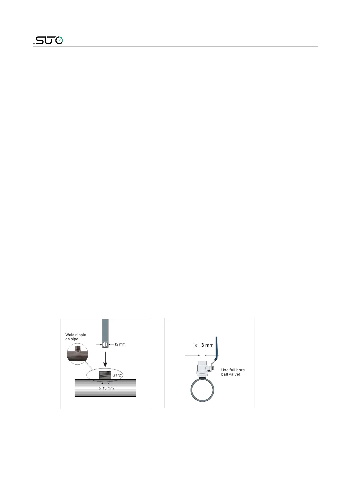
9.1 Installation requirements
To install the sensor, a ball valve or a nozzle is needed.
• The inner thread must be G 1/2”.
• The diameter of the hole must be ≥ 13 mm, otherwise the shaft can
not be inserted.
 Loading...