9 Sensor installation
9. Double check the installation depth because the shaft might be
pushed away from its original position by the compressed gas.
10. Tighten the locking nut with clamping torque 20 … 30 Nm.
9.2.3 Removing the sensor
1. Hold the flow sensor firmly.
2. Release the locking nut.
3. Pull out the shaft slowly until the value “10” can be read at the
scale.
4. Close the ball valve.
5. Release the connection head and unscrew the flow sensor.
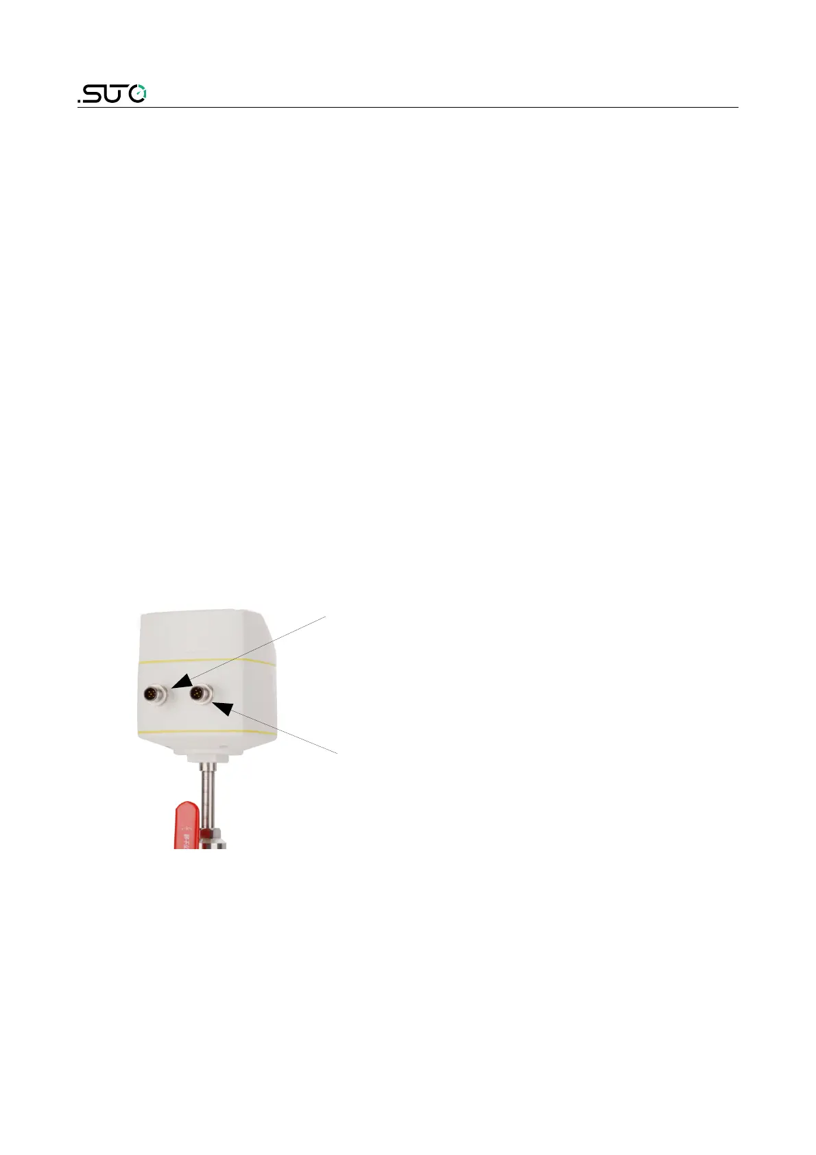
9.3 Electrical connection
The flow sensor is equipped with two Connector plugs “A” and “B”. The
cables are connected to the sensor through the M12 connector.
Connector A
Connector B