3-8 ENGINE CONTROL SYSTEM
SENSOR AND SWITCH
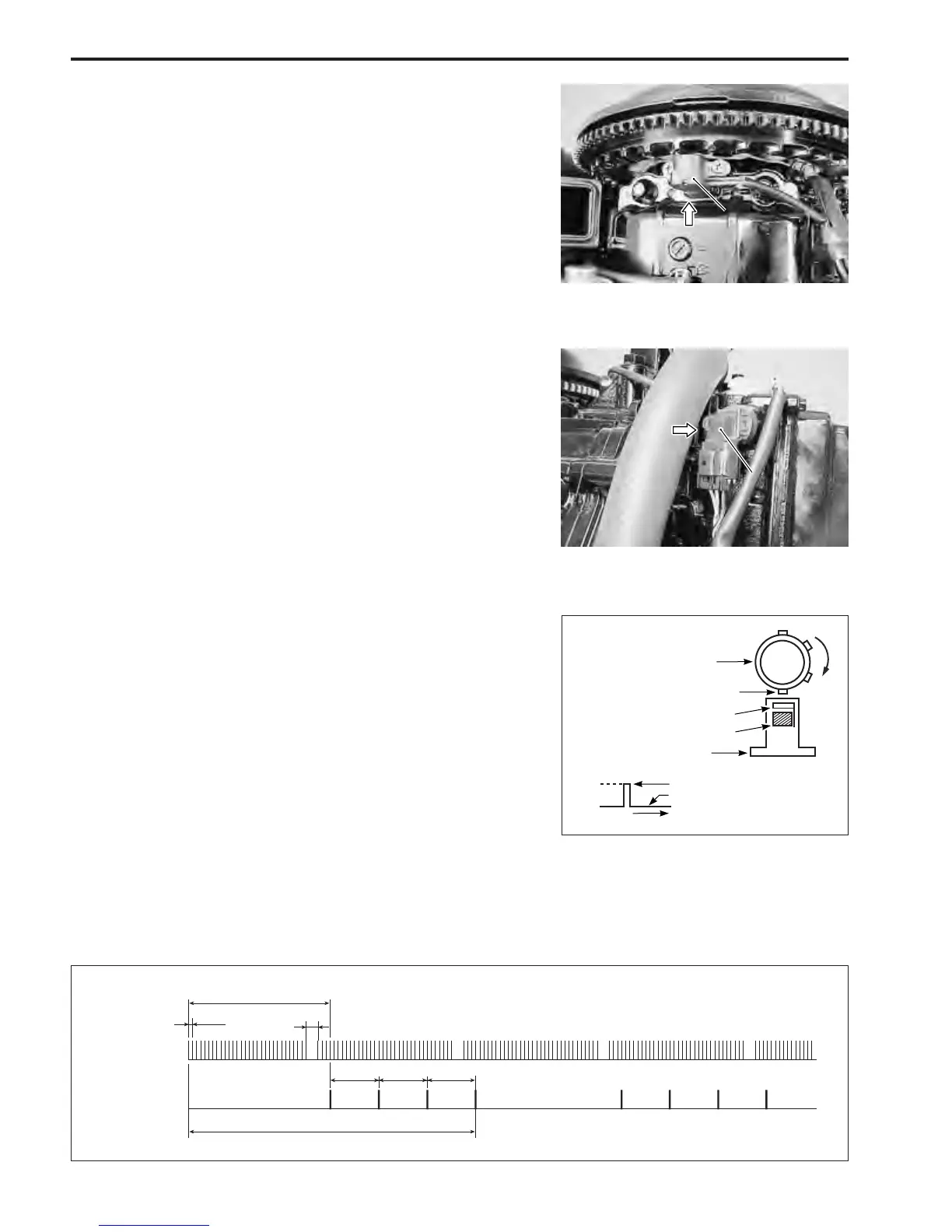
CKP (Crankshaft Position) SENSOR
There is one (1) CKP sensor installed below the flywheel rotor.
When the reluctor bars on the flywheel pass the sensor, a sig-
nal (voltage pulse) is generated and sent to the ECM.
This is the fundamental signal used to judge the engine speed
and crankshaft angle.
There are 34 reluctor bars, spaced 10 degrees apart, followed
by a larger index space. During one crankshaft rotation, 34 sig-
nals are input to the ECM.
CMP (Camshaft Position) SENSOR
A CMP sensor mounted on the cylinder head cover and trigger
vanes pressed onto the end of the exhaust camshaft are used
to detect piston position. The signal from this sensor is received
by the ECM which uses it to determine sequential fuel injection
control.
The CMP sensor contains a “Hall Effect” semiconductor and a
magnet. The semiconductor generates a voltage in proportion
to the line of magnetic force passed through it. When a trigger
vane on the camshaft reluctor aligns with the sensor’ internal
magnet, a large amount of magnetic force is generated allow-
ing a high voltage to pass through the semiconductor. When
the trigger vane moves away from the sensor, no magnetic force
is generated and low voltage passes through the semiconduc-
tor.
These generated voltages are rectified to create “ON” (high
voltage) & “OFF” (low voltage) signals to the ECM.
Four trigger vanes are provided on exhaust camshaft and dur-
ing one rotation of camshaft (two rotations of crankshaft), four
high voltage signals are supplied from CMP sensor to ECM.
ECM cylinder identification :
The cylinder is identified by a calculation combined from two sig-
nals ; one from the CKP sensor and one from the CMP sensor.
Camshaft
Trigger vane
“Hall Effect” semiconductor
Magnet
CMP sensor
High voltage
Low voltage
CKP sensor
CKP sensor
CMP sensor
CMP sensor
10˚
120˚ 120˚ 120˚
4-signals/720˚
34-signals/360˚
CKP sensor
signal
CMP sensor
signal
30˚
 Loading...


