FUEL SYSTEM 4-11
REASSEMBLY
Reassembly is reverse order of disassembly with special atten-
tion to the following steps.
FLOAT
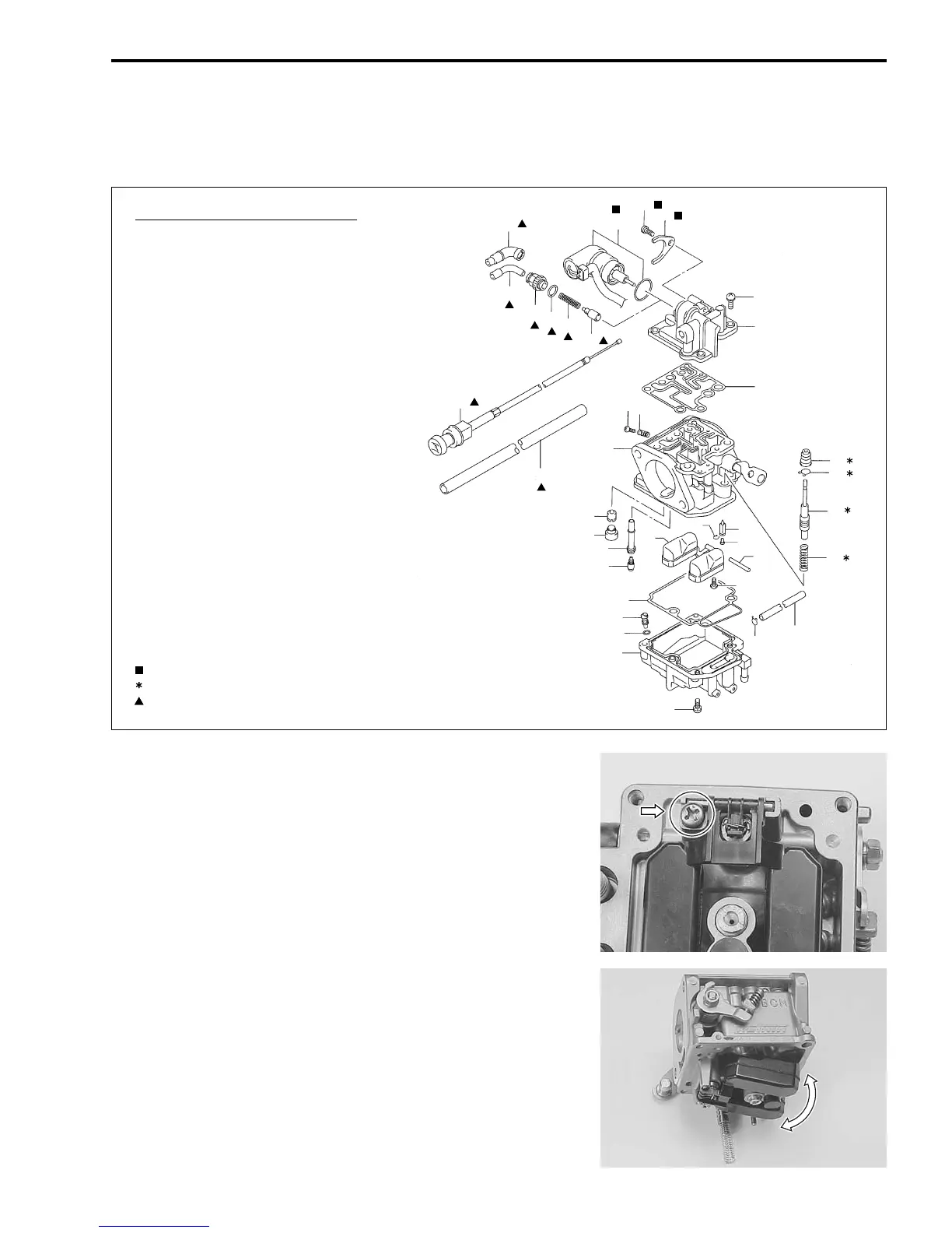
Install the float (with float pin and needle valve), then secure
float pin with the screw.
NOTE:
After installing float, inspect for smooth movement of float.
CONSTRUCTION DIAGRAM
1. Carburetor body
2. Main nozzle
3. Main jet
4. Pilot jet
5. Cap
6. Float
7. Needle valve
8. Needle valve pin
9. Clip
10. Pin
11. Screw
12. Stop screw
13. Spring
14. Gasket
15. Float chamber
16. Drain screw
17. O-ring
18. U-ring
19. Top cover
20. Screw
21. Cable holder
22. Cable guide
23. Cable sealing cap
24. Starter valve
25. Spring
26. O-ring
27. Drain hose
28. Clip
29. Plate
30. Screw
31. Starter assy
32. Clip
33. Cap
34. Plunger
35. Spring
36. Starter knob assy
37. Cable protector
23
22
21
26
25
24
31
30
29
20
19
18
36
37
1
4
5
2
3
14
16
17
15
20
28
27
35
34
32
33
11
10
8
7
9
6
12
13
marked item: For DF9.9R/15R only.
marked item: For DF15/E/R only.
marked item: For Tiller handle model only.