13
SV106 user's manual
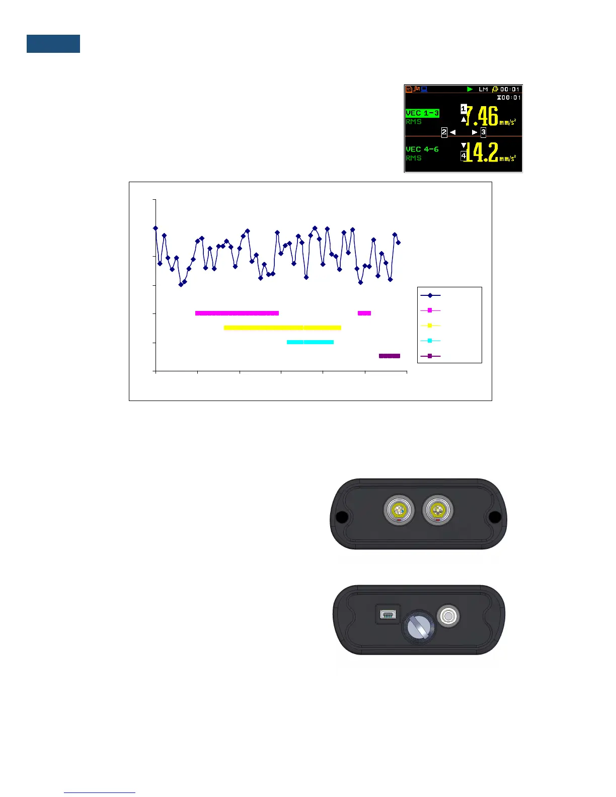
An example presentation of the markers on the time history plot is
shown below (to view a plot with markers the user has to transfer data
to the appropriate software such as Supervisor or SvanPC++).
20
30
40
50
60
70
80
13:30:00 13:30:09 13:30:17 13:30:26 13:30:35 13:30:43 13:30:52
Leq
Marker 1
Marker 2
Marker 3
Marker 4
2.2 Input and output sockets of the instrument
Top cover of the instrument
The measurement inputs are placed on the top cover of
the instrument: two 5-pin Lemo compatible sockets type
ENB.0B.304 for
Channels 1–3
and
Channels 4-6
, all
with IEPE power supply for the accelerometers.
Bottom cover of the instrument
In the bottom cover there are two sockets, placed from
the left to the right as follows:
USB
Device 1.1 interface
and multi-purpose input / output socket
I/O
.
The
USB
Device 1.1 interface is the serial interface working with 12 MHz clock. Thanks to its speed, it is
widely used in all PCs. In the instrument, the standard 4-pin socket is used described in more detail in
Appendix C.

 Loading...


