Maintenance
148
Drilling or Welding of Parts or
Accessories
The chassis is designed and built to precise
tolerances and must not be drilled or
welded (except in accordance with certain
AL-KO Accessory Operating Instructions).
Failure to comply will invalidate all
warranties.
Independent Suspension
The AL-KO rubber suspension is designed
and developed to suit all types of road
conditions and is maintenance free. Three
rubber elements are contained within a
hexagonal axle tube. These provide
suspension and have inherent damping
characteristics. (Only the hubs and wheel
brakes require attention - see axle section).
Loadings on Coupling Heads, Overrun
Assemblies and Axles
The permitted ‘nose’ weights of the coupling
head/stabiliser, overrun assembly and
drawbars, must never exceed the lowest
value stamped on the assemblies.
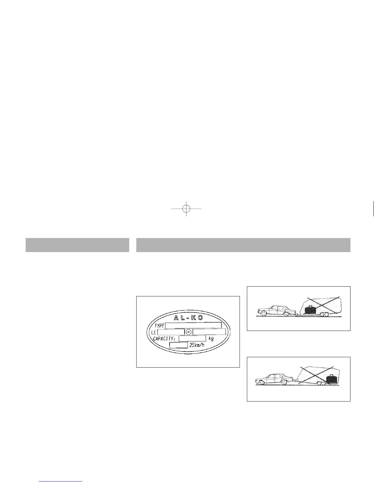
The maximum axle loading is that stamped
on the oval (Fig. 1) plate located in the
centre of the axle, facing rearwards. The
third line down marked “Capacity” is the
maximum permitted axle loading and
must not be exceeded.
Where the Caravan Manufacturer states a
maximum loading weight, then this is the
maximum permitted load. This figure must
not exceed the maximum axle load.
Enter your Axle details for future reference:
Loading
Loads to be carried in the caravan should be
placed directly over, or as close as possible
to the axles, otherwise the handling will be
impaired.
Maximum gross weight, as advised by the
caravan manufacturer, must not be
exceeded without approval from AL-KO.
Maximum loading is defined as the
difference between ex-works weight and the
permitted total weight.
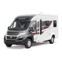
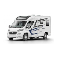
Load Too Far Forward (Fig 2)
Steering and braking ability reduced.
Increased loading on the rear axle and
chassis of the tow vehicle.
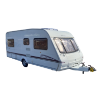
Load Too Far Back (Fig. 3)
High skid risk together with poor braking
effect.
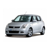
Load Over Axle (Fig 4)
Optimum road holding together with
maximum braking effect. Exceptionally heavy
loads should packed directly over the axle.
Attention should be paid to the legal
regulations regarding the permitted
pressure exerted by the towbar on the
towed unit.
Fig. 1
Fig. 2
Fig. 3
 Loading...