Maintenance
151
AL-KO BRAKING SYSTEM ADJUSTMENT
1. Ensure the towing shaft with coupling
head is pulled FULLY FORWARD. (Fig.
10).
2. Release the handbrake to the FULLY OFF
position. If the handbrake will not go
down the whole way because of the
fairing or any other obstruction; then the
fairing must be cut away and/or the
obstruction removed to achieve this
desired position. It will not be possible to
set up the braking system properly when
the handbrake is not in the FULLY OFF
position. (Fig. 10).
3. Jack up one side of the caravan, using
the AL-KO Side Lift Jack System. (see
Jack Operating Instructions).
4. Remove the inner plastic bung from the
backplate to expose the “starwheel”
adjuster access. (Figs. 10 & 11).
5. ALWAYS rotating the road wheel in the
forward direction - NEVER backwards;
adjust the starwheel with a suitable
screwdriver, in the direction of the arrow
embossed on the backplate until there is
resistance in the wheel rotation. (Fig. 11).
6. Slacken off the starwheel adjuster until
the road wheel turns freely in the
FORWARD direction. (Fig. 11).
7. Check the adjustment at the end of the
brake cable where it is secured to the
abutment (bracket), welded to the centre
of the axle. When the inner cable is pulled
out it should extend between 5 and 8
mm. (Fig.12). (On tandem axles a double
abutment (bracket) is fitted to the front
axle ONLY).
8. Repeat for other wheel or wheels.
9. On tandem axles the brake cables from
the rear axle should pass over this axle
and cross over each other, before being
connected to the abutment (bracket) on
the front axle.
10. Ensure the balance bar (compensator) is
being pulled evenly (Figs.10 & 12).
Excessive movement to this bar (double
on tandem axles) would indicate possible
incorrect adjustment (if appropriate,
repeat step No. 7 - Fig. 12).
11. Check the brake rod support bracket,
(fixed to the floor) IS supporting the
brake rod evenly. The brake rod MUST
ALWAYS run straight, NEVER bent or
curved under any fittings. On tandem
axles, using the double balance bar, a
brake rod support tube (Part No. 228827)
MUST ALWAYS be fitted on the end of
the brake rod, passing through the
centre aperture on the abutment.
12. Remove the slack in the brake rod by
adjusting the long ball nut, rear of the
balance bar, ensuring the overrun lever
makes contact with the end of the
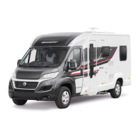
Fig. 7 Rebound or Free Position
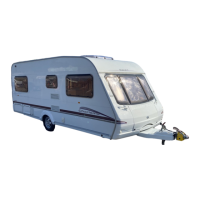
Fig. 8 Normal or Laden Position
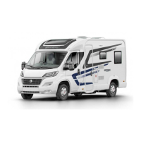
Fig. 9 Maximum Bump
 Loading...