IF THERE ARE ANY PROBLEMS DURING INSTALLATION OF THE FAN, THE INSTALLER MUST CONTACT THE
HUNTER PACIFIC INTERNATIONAL WARRANTY LINE . TEL: 1300 360 280BEFORE LEAVING THE WORK SITE
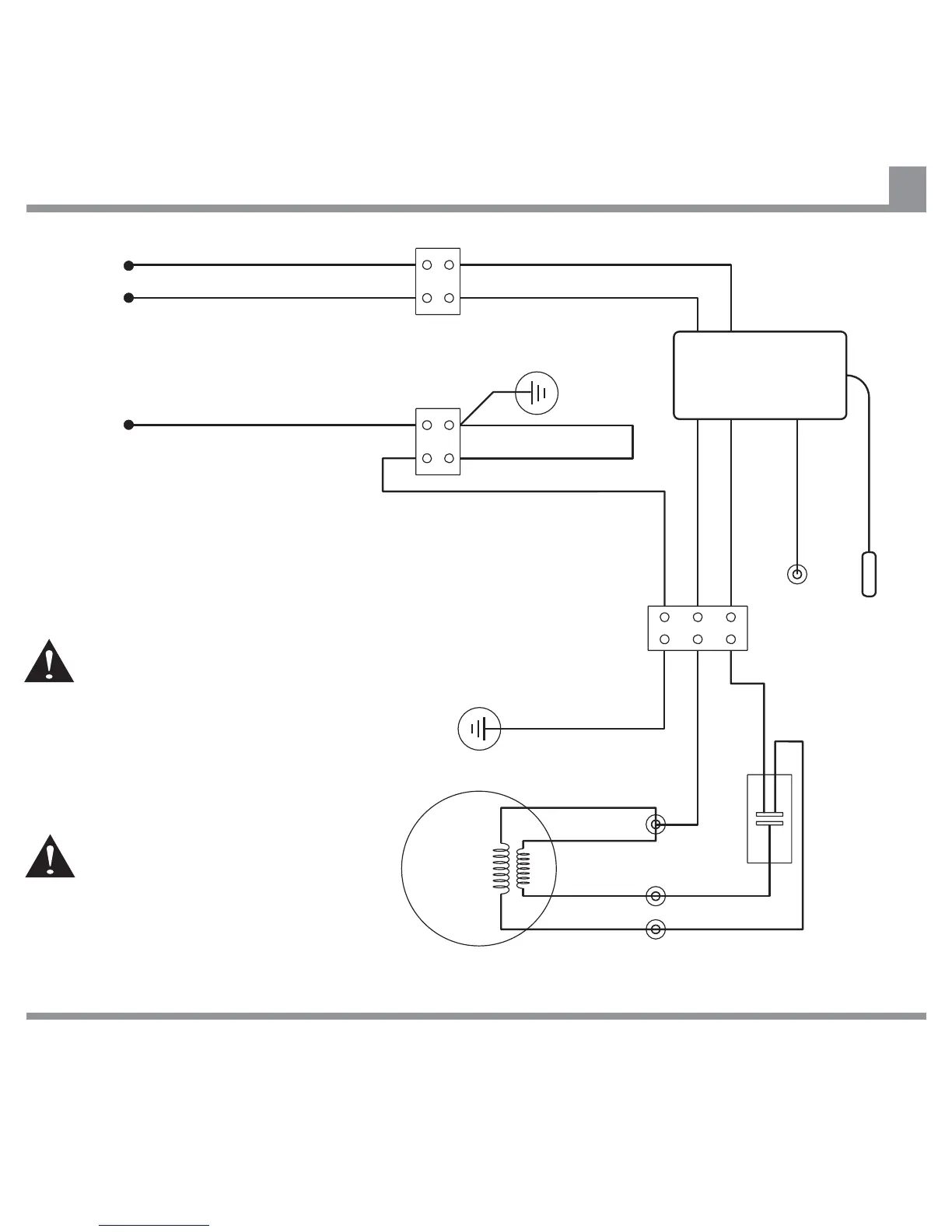
Note:
As shown, the Remote Control
Receiver is wired in series between
the Hanger Bracket terminal and the
Chassis terminal.
The SWITCHED LIVE (Active) wire
come via a Wall Switch. This
allows the fan to be manually
switched off, should a fault ever
develop.
MUST
Do not cut or shorten the Aerial wire
without folding the cut end over and
insulating with three layers of good
quality electrical insulation tape.
Remote Control (Accessory) Installation Wiring Diagram
25
SWITCHED LIVE (Active) from Wall Switch
NEUTRAL from Mains Supply
EARTH Conductor
E (Green/Yellow)
E (Green/Yellow)
(Purple)
(Yellow)
(Red)
(Orange)
(Red)
(Blue)
TO FAN (Blue)N
TO FAN (Brown)L
E (Green/Yellow)
L (Brown)
Ariel (Black)
For Light (White)
N (Blue)
Capacitor
Chassis
Terminal
Block
Remote
Control
Receiver
Hanger
Bracket
Earth
Chassis
Earth
Fan
Motor
Hanger
Bracket
Terminal
Blocks
AC IN (Brown)L
AC IN (Blue)N
M
1~
WARNING