17.ELECTRICAL SYSTEM
17-8
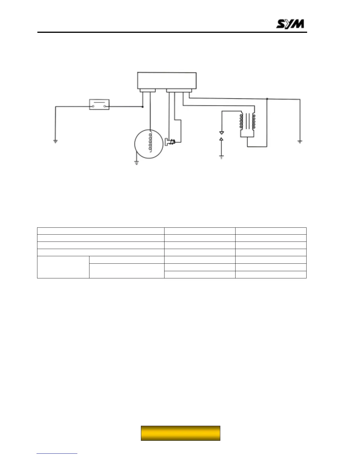
Ignition System
Ignition circuit diagram
C.D.I Assembly
Disconnect connectors of the C.D.I assembly.
Check the following connectors as indicated in the table at the harness side.
Item Points to check Result
Main switch Black/white/green
Exciting coil Black/red/green 100-200
Pulse generator Green/White/Blue/yellow 50-170
Primary circuit Black/yellow/green
0.17±10%
Black/yellow/with no cap
3.6±10%
Ignition coil
Secondary circuit
Black/yellow/with cap 7.3-11K
Main switch
Exciting
coil
Spark
plug
Ignition
coil
CDI assembly
Pulse
generator
Green
Black/yellow
Green
Black/red
Green/
white
Blue/
yellow
Black/white
To this chapter contents
 Loading...