17. Electrical System
17-18
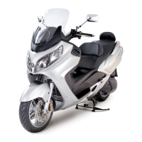
Left handle switch
Remove the handle cover and front cover.
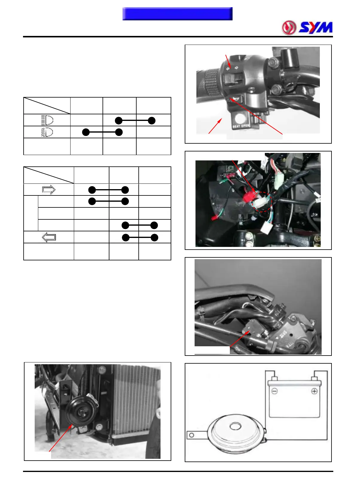
Disconnect the coupler of left handle switch.
Check the continuity between two points as
indicated in the table below
High and low beam switch
Winker switch
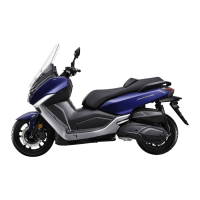
Brake Switch
While grasp the brake lever firmly, the terminals of
white/green and green/yellow of the brake should
have continuity.
Replace the switch if damaged.
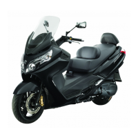
Horn
Remove the front cover and front under spoiler.
Apply 12 V power source to two terminals of the
horn, the horn should work.
Replace the horn if necessary.
Left handle switch coupler