4. Fuel Injection System
4-50
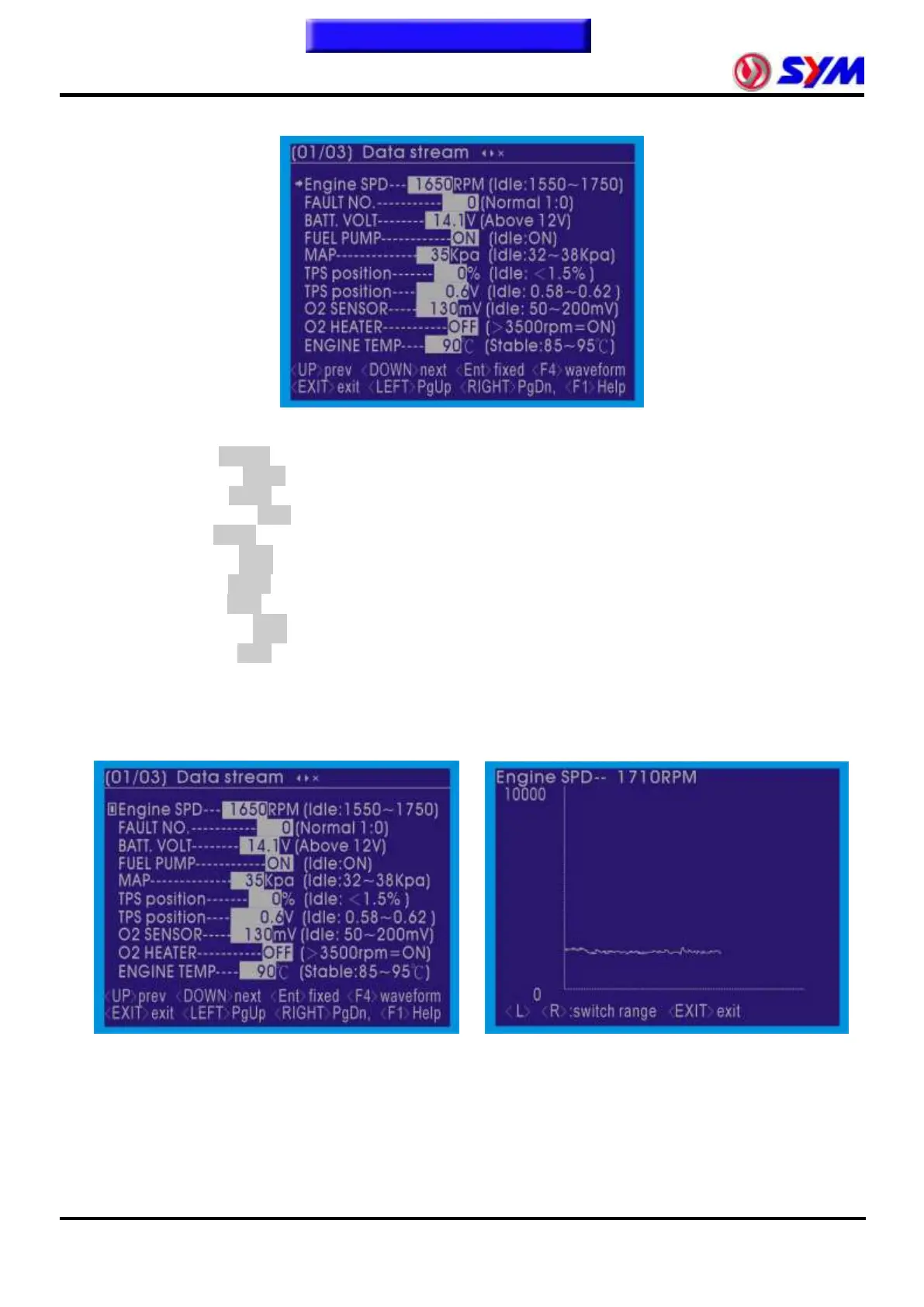
Data stream (1/3)
The screen showed the ECU captured by the engine of the state immediately.
The following data for the benchmark idling state:
● Engine SPD--- RPM (Idle:1550~1750) →Engine idle speed
● FAULT NO.-------- (Normal:0) →Fault code number
● BATT. VOLT---- V (Above 12V) →Battery voltage
● FUEL PUMP--------- (Idle:ON) →Fuel pump actuator state
● MAP------------ kPa (Idle:32~38kPa) →Manifold pressure
● TPS position------ % (Idle:﹤ 1.5%) →Throttle opening
● TPS position---- V (Idle:0.58~0.62) →Throttle sensor voltage
● O
2
SENSOR---- mV (Idle:50~200mV) →O
2
sensor voltage
● O
2
HEATER--------- (Idle:﹥ 3500rpm=ON) →O
2
heater actuator state
● ENGINE TEMP-- ºC (Stable:85~95ºC) →Engine temperature (cooling water temperature)
In the "DATA STREAM" of the screen use "▲" "▼" button to move the left side of the project "→"
symbol selected items, press the "ENTER" button lock of the project, and press the "F4" button
showed that the wave of projects.
Able to use "◄ left" and "right ►" button, can transform View wave numerical size.
Numerical analysis of images (1 / 3), the waveform can be displayed as shown in the following items:
Engine SPD
BATT. VOLT
MAP
TPS position %
TPS position Voltage
O
2
SENSOR Voltage
ENGINE TEMP