DOC 6511_Release K
ATS-6511A/B/C Users Guide
7
2.4.2 Output Cards
The ATS-6511 has the capability using six output cards in each unit. The cards slots are
identified by number so the operator is capable of determining the slot of the card in the show
command and identifying the cards physical location in the chassis. Figure 1 shows the rear panel
layout of the unit from left to right.
Slot 1 Slot 3 Slot 5
Slot 2 Slot 4 Slot 6
Figure 1 Rear Panel Output Card Locations
The ATS-6511 will operate with six different types of output cards. All output cards except the
4399A can be operated in any of the six slots. The 4399A is a double wide module that can only
be installed in slots 3 and 5. The divider between Slots 3 and Slot 5 must be removed to
accommodate installation of the 4399A L-Band module. To remove this divider, remove
modules that are installed in these slots. Remove the screw located on the top of this divider.
After removing this screw, pull the divider out the back of the chassis and install the 4399 Card.
Once the card is installed power cycle the unit to allow the system to start up with the current card
configuration.
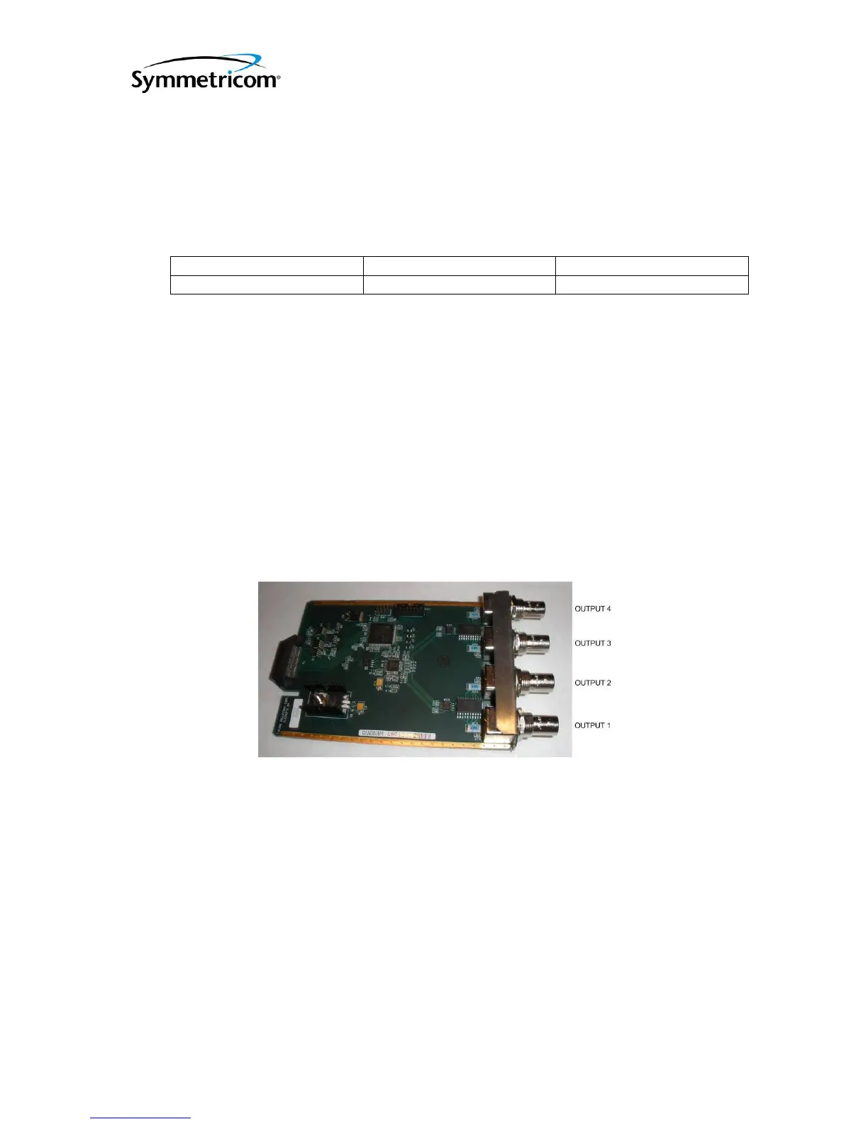
At start up the unit will automatically detect and configure the system based on the cards
installed. The cards are also hot swappable. Each of the standard output cards has four output
connectors with the output number identified as shown below in Figure 2. See Appendix A for
the specifications of each output module.
Figure 2 Single Slot Output Module
2.4.2.1 4394A (PPS/DC IRIG)
The factory default for this module provides two 1PPS outputs and two DC IRIG (B000) Outputs.
The default configuration sets Outputs 1 and 2 to 1PPS and Outputs 3 and 4 to DC IRIG. The
output types are user selectable/programmable. Users can change the signal types (PPS/DC
IRIG), the PPS signal parameters, and the IRIG signal types on individual output ports.
• PPS: Valid PPS settings are 1, 10, 100, 1K, 10K, 100K, 1M PPS and 10M PPS. To
set the PPS signal parameters use the pps command:
ATS-6511> pps [slot#] [port#] [pulse period] [pulse width]
 Loading...