1-7-5 T2127EA
5. H f
0
Adjustment
Purpose: To get correct horizontal position and size of
screen image.
Symptom of Misadjustment: Horizontal position and
size of screen image may not be properly displayed.
Note: R2583 --- Sub CBA
1. Connect frequency counter to R2583.
2. Operate the unit for at least 20 minutes.
3. Enter the Service mode. (See page 1-7-1.) Press
[2] button on the remote control unit and select H-
ADJ mode.
4. Press [CH. o / p] buttons on the remote control
unit so that the display will change "0" to "7."
5. At this moment, choose display "0" to "7" when the
frequency counter display is closest to
15.734kHz±300Hz.
6. Turn the power off and on again.
6-1. Cut-off Adjustment
Purpose: To adjust the beam current of R, G, B, and
screen voltage.
Symptom of Misadjustment: White color may be
reddish, greenish or bluish.
Notes: Screen Control --- FBT (Sub CBA), FBT= Fly
Back Transformer,
Use the Remote Control Unit.
1. Degauss the CRT and allow the unit to operate for
20 minutes before starting the alignment.
2. Input the Black raster signal from RF input.
3. Enter the Service mode. (See page 1-7-1.)
4. Press the [VOL p] button.
(Press [VOL p] then display will change CUT OFF/
DRIVE and 7Fh adjustment).
5. Choose CUT OFF/DRIVE mode then press [1] but-
ton. This adjustment mode is CUT OFF (R).
6. Increase the screen control so that the horizontal
line just appears on the CRT.
7. Press the [CH. o / p ] button until the horizontal
line becomes white.
8. Choose CUT OFF/DRIVE mode then press [2] but-
ton. This adjustment mode is CUT OFF (G). Press
[CH. o / p] until the horizontal line becomes white.
9. Choose CUT OFF/DRIVE mode then press [3] but-
ton. This adjustment mode is CUT OFF (B). Press
[CH. o / p] until the horizontal line becomes white.
10.Turn the power off and on again.
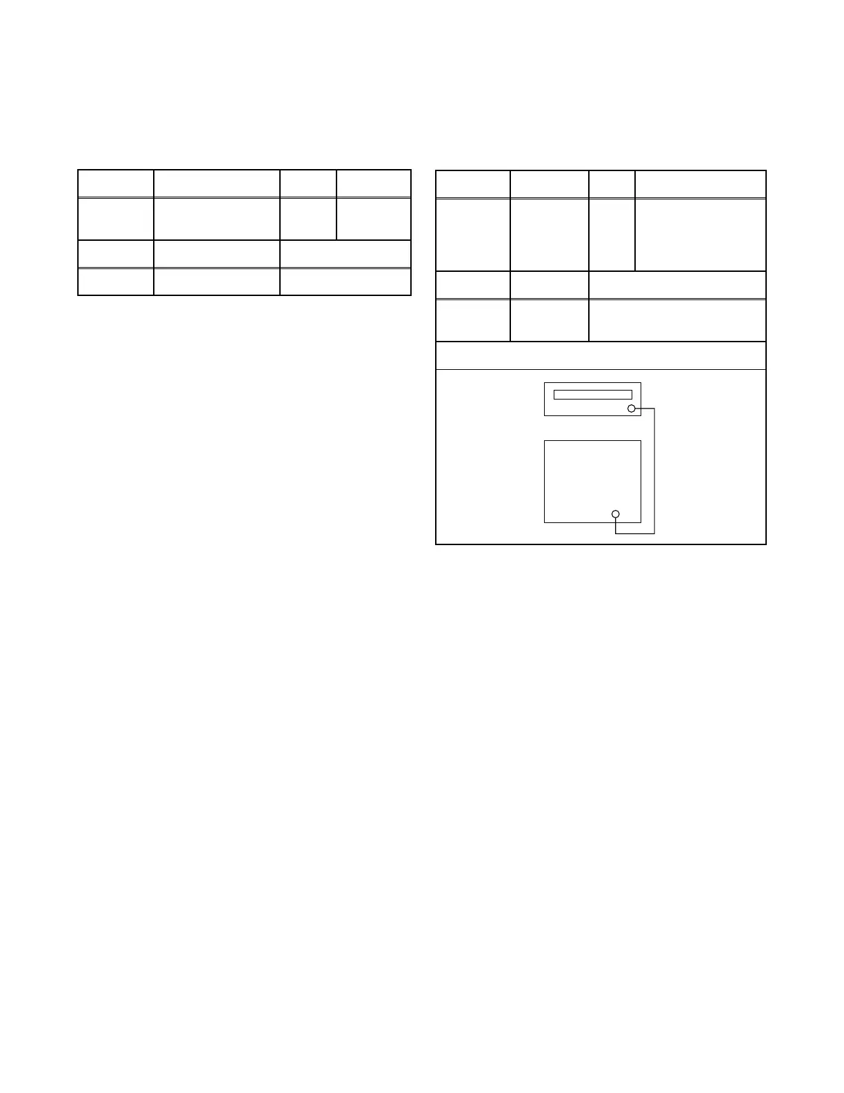
Test point Adj. Point Mode Input
R2583
CH. o / p
buttons
Video ---
Tape M. EQ. Spec.
--- Frequency Counter 15.734kHz±300Hz
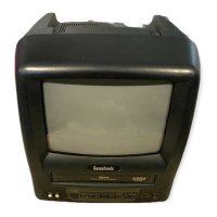
Test point Adj. Point Mode Input
---
Screen-
Control
CH. o / p
buttons
RF Black Raster
Tape M. EQ. Spec.
---
Pattern
Generator
See Reference Notes below
Figure
Fig. 5
PATTERN GENERATOR
RF INPUT