30 Synopsys, Inc.
SolvNetPlus
DesignWare
5.60a
March 2020
Setting Up Hardware Components PCIe IP Prototyping Kit Installation Guide
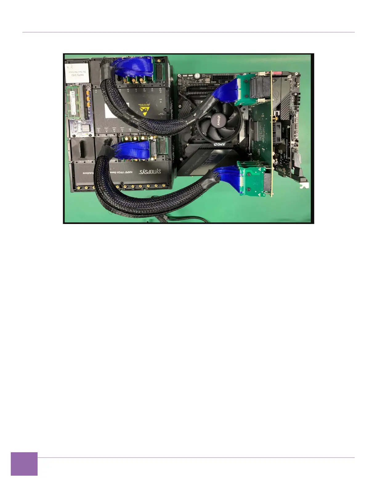
Figure 1-21 PCIe Endpoint IP Prototyping Kit Setup Using E32 PHY Board
1. Connect the E32 PHY board to HAPS-80:
a. Use CABLE40_HT3 cables, and connect HT3 ports 20, 21, 22 and 23 on the HAPS-80 and HT3
ports 4 ,3 ,2 and 1 respectively, on the E32 PHY.
Also connect HT3 8, 9, 10 and 11 on the HAPS-80 and HT3 connectors 5, 6 ,7 and 8, respectively, on
the E32 PHY to mechanically connect the boards.
2. Complete the following hardware power-up sequence to ensure proper inter-board communication.
a. Power up the HAPS-80 board. Connect the HAPS-80 power supply. During the power-up
sequence, the supervision LEDs (RESET, READY, ALERT, and PWR) change color. After a
successful power-up sequence, all LEDs must be green (see Appendix A.2, “HAPS-80 Power-Up
Sequence”). The LED marked UDONE indicates if the FPGA is configured.
b. Power up the computer on which you are running the system. The HAPS-80 board LED1 turns
green to indicate the PCIe link connection (see “Appendix A.2, “HAPS-80 Power-Up Sequence”).