SYNTHES 9
8
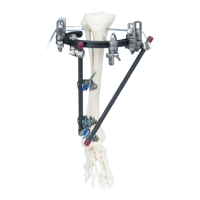
Insert the DHS/DCS screw
Slide the insertion instruments (see page 17 for assembly)
over the guide wire and advance the long Centering Sleeve
(388.190) into the drilled hole. Insert the DHS/DCS screw
(in this example 110 mm) until the zero mark reaches
the lateral cortex. Continue inserting the screw for a further
5 mm if the bone is osteoporotic.
The handle of the DHS/DCS Wrench (338.060) must
remain parallel to the femoral axis since only in this screw
position can the DHS plate be positioned correctly
over the flat-sided shaft of the DHS/DCS screw against
the femoral shaft.
Note: Do not use the DHS/DCS wrench to reduce the
fracture as this only allows limited transmission of forces.
Remove the DHS/DCS wrench and the long centering sleeve.
9
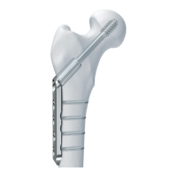
Position DHS plate
Position the DHS plate over the short Connecting Screw
(338.200) against the femoral shaft. Loosen the connecting
screw and remove the Guide Shaft (338.210).
Set the power tool to reverse operation to remove the guide
wire. Dispose of the guide wire.
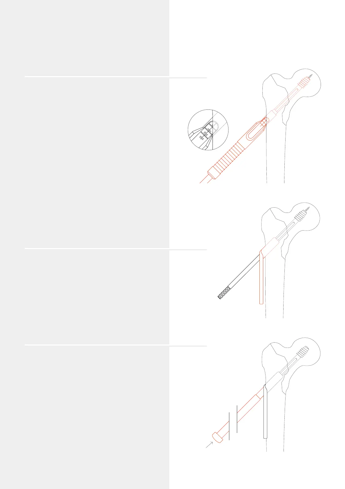
10
Tap DHS plate
Tap the DHS plate into the predrilled channel using
the DHS/DCS Impactor (388.140). Compress the fracture by
gentle hammer taps against the impactor.
Option
Where a Trochanter Stabilizing Plate (281.869 or 281.870)
is indicated, perform steps 11b–13b on page 11.
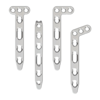
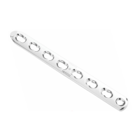
DHS/DCS Standard System
DHS plate
 Loading...