SYNTHES 13
4
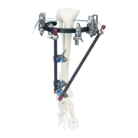
Determine entry point for the DHS/DCS screw and
insert guide wire
The entry point for the DHS/DCS screw is on the femoral
shaft axis approx. 2 cm from the knee joint.
Using two Kirschner wires determine the correct alignment
of the DHS/DCS screw.
– The first Kirschner wire in the frontal plane (a) marks
the orientation of the knee joint cavity at the level of the
condyles.
– Insert the second Kirschner wire (b) ventrally over the
lateral and medial condyles to demonstrate the incline of
the femoropatellar joint surface.
– Insert the DHS/DCS Guide Wire 2.5 mm (338.000) (c)
at the predetermined entry point such that it runs parallel
both to the first Kirschner wire (a) in a.p. view and to
the second, ventrally located wire (b) in the axial view. Insert
the guide wire until the medial cortex is reached.
Remove the Kirschner wires.
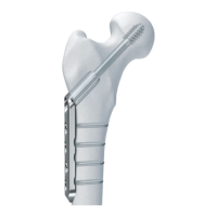
Determine entry point in the proximal femur
Using the Condylar Plate Guide (333.200), determine the
correct alignment of the DHS/DCS guide wire.
The entry point is located at the transition from the ventral
third to the mid-third of the greater trochanter, since the
guide wire in the femoral neck – in relation to the Lauenstein
projection – must be inserted in the centre.
Determine the 95° alignment to the axis of the femoral
shaft using the DCS Angled Guide (338.420) or the Condylar
Plate Guide (333.200).
5
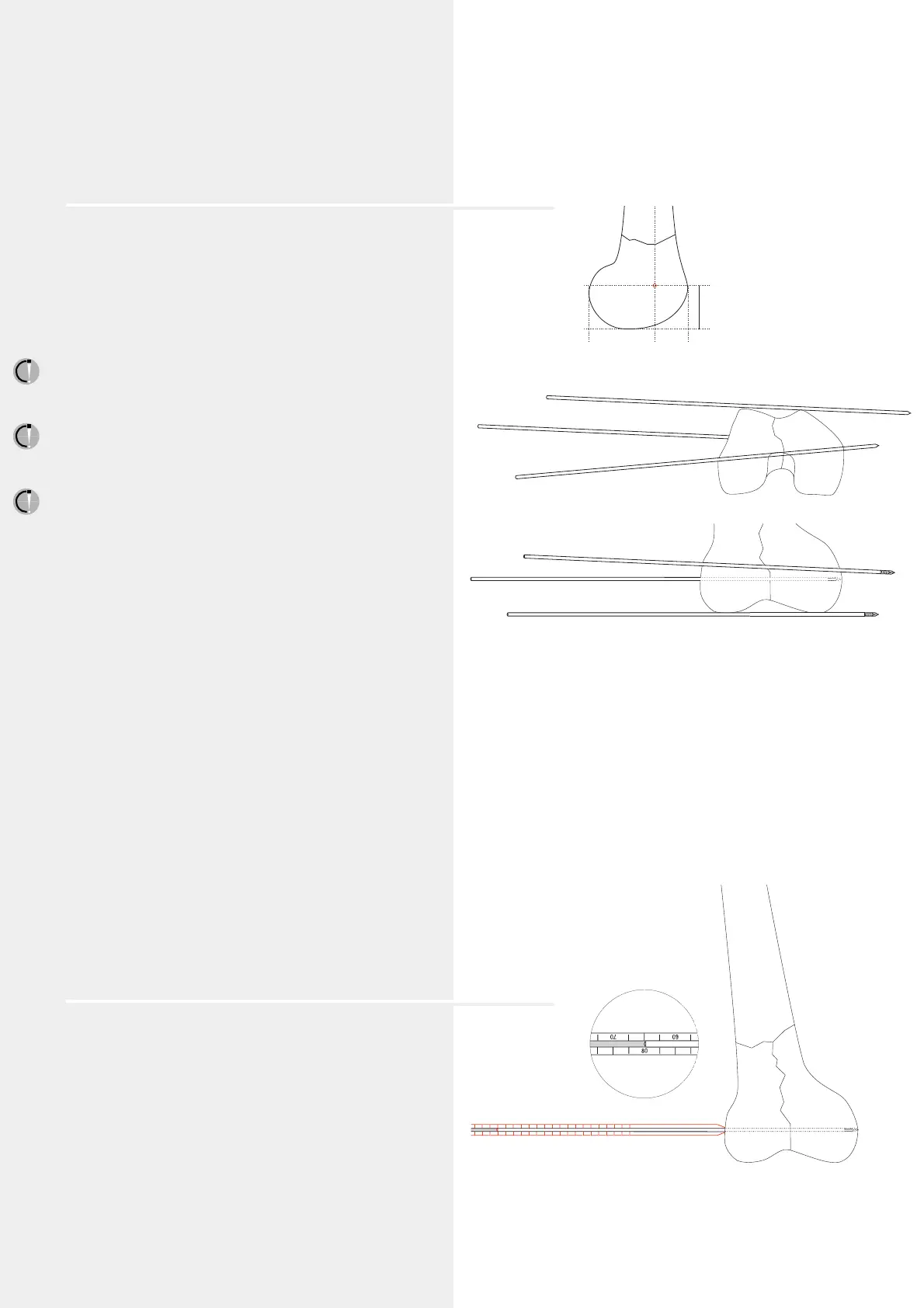
Measure the length of the guide wire
Slide the DHS/DCS Direct Measuring Device (388.050)
over the guide wire and determine the length (in this example
80 mm).
a
b
c
2
/
3
1
/
3
2 cm
a
b
c
 Loading...